Advertisement
INSTRUCTION MANUAL
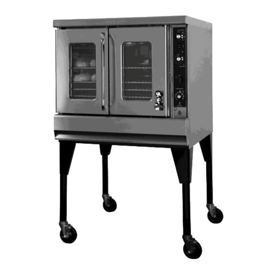
MONTAGUE
Gas Convention
Ovens
MODELS:
70, 115, R85, 2-70, 2-115, & R2-85 Series
These instructions should be read thoroughly before attempting installation.
Set up and installation should be performed by qualified installation personnel.
Keep area around appliances free and clear from combustibles.
PLEASE RETAIN THIS MANUAL
FOR FUTURE REFERENCE.
THE MONTAGUE COMPANY
1830 Stearman Avenue
P.O. BOX 4954
Hayward, CA 94540-4954
TEL: (510) 785-8822 FAX: (510) 785-3342
Advertisement
Table of Contents

Related Manuals for MONTAGUE Vectaire 70 Series


Summary of Contents for MONTAGUE Vectaire 70 Series
- Page 1 Set up and installation should be performed by qualified installation personnel. Keep area around appliances free and clear from combustibles. PLEASE RETAIN THIS MANUAL FOR FUTURE REFERENCE. THE MONTAGUE COMPANY 1830 Stearman Avenue P.O. BOX 4954 Hayward, CA 94540-4954 TEL: (510) 785-8822 FAX: (510) 785-3342...
-
Page 2: Table Of Contents
IMPORTANT TABLE OF CONTENTS Important (Cautions and Warnings) ............Page 1 Installation ....................Page 2 - 10 Operation ...................... Page 11 - 12 Cooking Hints ....................Page 13 - 17 Maintenance ....................Page 18 - 20 Maintenance Schedule ................Page 21 Service ...................... -
Page 3: Important (Cautions And Warnings)
IMPORTANT FOR YOUR SAFETY WARNING IMPROPER INSTALLATION, ADJUSTMENT, ALTERATION, SERVICE OR MAINTENANCE CAN CAUSE PROPERTY DAMAGE, INJURY OR DEATH. READ THE OPERATING AND MAINTENANCE INSTRUCTIONS THOROUGHLY BEFORE INSTALLING OR SERVICING THIS EQUIPMENT. WARNING DO NOT STORE OR USE GASOLINE OR OTHER FLAMMABLE VAPORS AND LIQUIDS IN THE VICINITY OF THIS OR ANY OTHER APPLIANCE. -
Page 4: Installation
INSTALLATION Vectaire convection ovens with the national fuel code, ANSI Z223.1-latest manufactured for use with the type of gas and addenda, including: electric supply indicated on the nameplate 1. The appliance and its individual shutoff behind the fire box panel. valve must be disconnected from the gas The Vectaire oven is produced with the best supply piping system during any pressure... - Page 5 INSTALLATION 2. Do not mount the oven on a curb unless it 6” LEGS: SUITABLE FOR INSTALLATION has been equipped with the No. 555 Toe Base (P/N: 06024-0) for this type of Location Combustible Noncombustible installation. Construction Construction 6” 5” 3.
- Page 6 INSTALLATION Model 70, 115, SL70 and SL115 series and P/ N: 03099-6 for Model 2-70, 2-115, SL2-70 and SL2-115 series must be used. The flue should rise at least 10 feet above the roof or any surrounding structure. The flue should rise at least feet above...
- Page 7 INSTALLATION Tighten the knurled lock nut by hand until the caster is secure inside tube of leg. Secure the Caster Restraint Mount to the bottom of the oven directly below the gas inlet pipe. Use the hex head screws supplied.
- Page 8 INSTALLATION When the oven is in permanent position, level entire unit by placing a carpenter’s level on the oven rack and adjusting the foot on the bottom of each leg so that the oven is level from front to back and side to side. Vectaire Models: 2-70, 2-115, SL2-70 &...
-
Page 9: 8" Oval Vent
INSTALLATION Flue Deflector SS P/N: 16539-5 Drafthood SS P/N: 3099-6 FOR 8” VENT PIPE Flue Box SS P/N: 16532-8 Flue Riser Alzd P/N: 4437-7 SS 4445-8 Flue Riser Alzd P/N: 4437-7 SS 4445-8 Flue Collector Alzd P/N: 4439-3 Flue Collector Alzd P/N: 4439-3 SS 4443-1 SS 4443-1 (Figure 4) - Page 10 INSTALLATION 5. When oven is in permanent position, level holes with the holes on the bottom of the entire unit by placing a carpenter’s level on oven. Secure the leg using the provided 3/8” the oven rack and adjusting the foot on the bolts and washers.
- Page 11 INSTALLATION horizontal flue collector. Secure in place with This gas pressure regulator is factory adjusted self-drilling sheet-metal screws. Install the flue for 3.5” Water Column (W.C.) manifold deflector over the flue outlet of the upper R85 pressure. The maximum inlet pressure to the unit.
- Page 12 INSTALLATION three phase units. The wiring diagram is located on the back of the oven. WARNING THIS APPLIANCE, WHEN INSTALLED, MUST BE ELECTRICALLY GROUNDED IN ACCORDANCE WITH LOCAL CODES, OR IN THE ABSENCE OF LOCAL CODES, WITH THE NATIONAL ELECTRICAL CODE, ANSI/NFPA No.
-
Page 13: Operation
OPERATION GAS CONTROL SYSTEM (ALL MODELS Turn fan off. EXCEPT WITH SUFFIX “EI”) Turn electrical service off Lighting disconnect electrical supply cord from wall receptacle. Turn on main gas shutoff valve and electrical service. Relighting (Standard Pilot) In the event a gas odor is detected, shut 1. - Page 14 OPERATION 2. Turn thermostat to lowest setting. CONTROLS (STANDARD MODELS) (MODELS WITH SUFFIX “AE, AG, ZE, ZG”) 1. “LIGHT-OFF” switch controls the oven interior lights. 2. Four position rotary switch controls the fan operation. It must be on to obtain satisfactory performance.
-
Page 15: Cooking Hints
COOKING HINTS temperatures, and moisture contents may vary USING A CONVECTION OVEN in other convection ovens. The suggested The convection oven is a different type of times temperatures vary oven which offers many features considerably from those shown. They are advantages to the food service operation. - Page 16 COOKING HINTS Guide to Time and Temperature Product Temperatures Time Racks Used Bread, Bakery Bread (24-1 lb. Loaves) 340 degrees F 30 min Hamburger Rolls 300 degrees F 15 min Corn Bread (Northern) 335 degrees F 25 min Corn Bread (Southern) 375 degrees F 15-20 min Yeast Rolls...
- Page 17 COOKING HINTS Guide to Time and Temperature Product Temperatures Time Racks Used Rolled Beef Roast (12-15 lb.) 250 degrees F 2 1/2 hours Steamship Round (80 lb.) 275 degrees F 2 3/4 hours Steaks - New York 450 degrees F 7 min Steaks - Salisbury 300 degrees F...
- Page 18 COOKING HINTS BAKING DIFFICULTIES & PROBLEM SUGGESTIONS CAUSES Avoid recipes that would satisfactory in a regular conventional oven. Good baking is a delicate operation and many operational factors enter into it. Times and temperatures will vary slightly with maximum to minimum oven loads. Pans which warp or buckle under hear always result in poor bakes.
- Page 19 COOKING HINTS Oven not level causing dough to run to Incorrect temperature. side or rear of pan. Cracked Cakes Spotty Pie Bottoms/Bread Too high temperature. Overworked pastry/dough. Too fast cooling. Burned Goods, Cripples Underdone Pie Bottoms (Advisable to Bake Incorrect temperature.
-
Page 20: Maintenance
MAINTENANCE CAUTION Exterior DISCONNECT POWER BEFORE CLEANING PAINTED SURFACE OR SERVICING. EACH OVEN SECTION Allow equipment to cool before cleaning HAS A SEPARATE ELECTRICAL SUPPLY exterior surfaces. Painted surfaces should be CONNECTION. cleaned using a mild soap and warm water solution on a sponge or soft cloth. - Page 21 MAINTENANCE bright for years to come. Stainless is hard, rust CAUTION -resisting metal that adds beauty and luster to NEVER ABRASIVES, POWDERS, countless household products. HARSH LIQUIDS, CAUSTICS, OR DYES AS THEY MAY LEAVE A FILM OR RESIDUE Helpful Hints THAT WILL CLOG THE PORES OF THE To remove streaks, rub stainless steel ...
- Page 22 MAINTENANCE CAUTION NOTE: The motor should be periodically CARE SHOULD BE USED WHEN WASHING cleaned of grease debris and lint. Keep vent DOWN EQUIPMENT TO KEEP WATER AND clean for peak performance. CLEANING SOLUTIONS OUT OF THE MOTOR OR DAMAGE WILL OCCUR. NOTE: Lack of maintenance may result in pre Blower Wheel -mature failure of components.
-
Page 23: Maintenance Schedule
MAINTENANCE Product Maintenance Schedule Components May June July Aug Sept Door Seals Motor Motor Insulation Door Bearings Thermostat Door Switch Turnbuckles 1,3,5 1,3,5 Fan Switch Blower Wheel Timer Oven Racks* Pilots Pilot Safety Burner Regulator Thermocouple (1) Inspect (2) Clean (3) Adjust (4) Replace (As Needed) (5) Lubricate... -
Page 24: Service
SERVICE MAIN BURNER DOOR ADJUSTMENT While your oven has been factory adjusted, it Procedure sometimes happens that the actual operating Right hand door on oven does not close conditions are different. Therefore, it may be when left hand door closes. Loosen necessary to make a field adjustment to turnbuckle 1 and tighten turnbuckle 2 (See secure satisfactory performance. -
Page 25: Service
SERVICE DOOR SWITCH ADJUSTMENT (MODELS Remove control panel. WITH SUFFIX “A”) Loosen top locknut on door switch. Before adjusting door switch, make sure fan Raise or lower bottom locknut so that when switch is in “fan” instead of “cool” position. the door is closed, the plunger on the Electrical circuit in “cool”... - Page 26 SERVICE thermostat is not maintaining proper oven By-Pass (Minimum Burner Flame) temperature. Before recalibration This adjustment must be checked at the time attempted, the oven temperature should be appliance is installed. checked using a good grade thermometer. Avoid laser thermometer. To Adjust By-Pass (Be Sure Pilot Flame is Ignited) GAS THERMOSTAT (Models With Suffix...
- Page 27 SERVICE 3. The heat indicating light will switch from Thermostat Calibration Check “OFF” when the thermostat turns off the 1. Place the lead of test instrument or burner. thermometer in the middle of the oven, or medium to be tested. 4.
- Page 28 SERVICE light sockets. Thermocouple Output REMOVAL OF MAIN BURNER AND PILOT Open Circuit MV Range BURNER Normal 25-35 Not Less Than 17 1. Remove burner box panel for access. 2. Turn off gas supply to oven. Remove single screw at front of burner on the left side.
- Page 29 SERVICE COMBINATION SAFETY PILOT VALVE & GAS PRESSURE REGULATOR AUTOMATIC GAS VALVE (FOR R85 & SOLID STATE UNIT WITH STANDING WARNING PILOTS) UNTRAINED PERSON SHOULD ATTEMPT TO MAINTAIN OR SERVICE THE GAS PRESSURE REGULATOR. Remove Screws (Figure 17) REMOVAL OF BURNER BOX FRONT AND BURNER BAFFLE Safety &...
- Page 30 SERVICE motor and oven back will have to be forced to fit round 10" hole. Pull motor through hole and rest on oven bottom. Reach behind plate and remove top of electrical box mounted on motor. Mark or identify wires for reconnection. Disconnect wire and remove flex from motor.
- Page 31 SERVICE (A) Bolt (F) Gear Rack Pull Forward Bearing (Figure 20) (Figure 22) Adjusting Door Seal It is important that the door seal be maintained across entire door but not too tight. 1. Loosen Bolts “D.” 2. Doors will slide up or down. 3.
- Page 32 SERVICE NOTE: If after doors are synchronized 6. Thermocouple defective. there is not enough adjustment in bolt holes 7. Thermocouple connection on safety pilot “D,” it will be necessary to loosen Bearing “E,” loose. move Gear Rack “F” up or down one tooth as needed.
- Page 33 SERVICE 3. Door out of synchronization. Oven Controls Overheating 1. Hole in top covered. 4. Upper door hits top before stops on lower door makes a contact. 2. Range installed on control side conducting heat to control compartment, (insulate side of oven).
- Page 34 SERVICE Model with Suffix “E” — 2 Speed Model with Suffix “G” — 2 Speed Motor Motor Model with Suffix “E” Model with Suffix “E” — 50 Hz 480V, 60Hz, 3 PH w/ 120V Control Circuit...
- Page 35 SERVICE R85 KITS Single Unit Accessory Kit - Black includes: Gusset Legs; Single Unit Flue 29241-9 Deflector; Attaching Hardware Single Unit Accessory Kit - SIS includes: Gusset Legs; Single Unit Flue 29242-7 Deflector; Attaching Hardware Double-stack Accessory and Flue Kit - Black includes: 6" Legs; Double- 29243-5 stack Flue Deflector;...
-
Page 36: Orifice Size Chart - Drill Size
ORIFICE SIZE CHART - DRILL SIZE NOTE: Orifice size may vary depending on country of destination and/or elevation. Nat. 3.5 W.C. (8.71 mbar) Orifice #19 Part Number 17667-2 LP 10.0 W.C. (24.90 mbar) Orifice #36 Part Number 2361-2 Nat. 3.5 W.C. (8.71 mbar) Orifice #11 Part Number 1044-8 LP 10.0 W.C. - Page 37 PARTS VIEW - 115A...
- Page 38 PARTS VIEW - 115A...
- Page 39 PARTS VIEW - 115A...
-
Page 40: Exploded View Parts List
EXPLODED VIEW PARTS LIST 115A Series Vectaire Gas Convection Oven 1 ..03395-2 ..Thermostat, Gas (FDO) ..36386-3 ..Manifold, Main (3/4")-R85 ..03499-1 ..Thermostat, Electric (KX) 115E, R85E 42 ..36120-8 ..Manifold, Lower (1/2") 2 ..01025-1 ..Safety Valve, Gas Thermostat .. - Page 41 PARTS VIEW...
- Page 42 PARTS VIEW...
- Page 43 EXPLODED VIEW PARTS LIST 15Z Series Vectaire Gas Convection Oven 1 ..03395-2 ..Thermostat, Gas (FDO) ..03578-5 ..Trunnion, Upper Door ..03499-1 ..Thermostat, Electric (KX) ..03575-0 ..Trunnion, Lower Door 2 ..01025-1 ..Safety Valve, Gas Thermostat ..
-
Page 44: Wire Diagram
WIRE DIAGRAMS... - Page 45 In order to establish full compliance with Proposition 65, we attached a yellow warning label to each gas fired unit manufactured by the Montague Company. Carbon monoxide would not be present in concentrations that would pose a "significant risk" to the consumer when the equipment is installed, operated and maintained as follows: 1.
- Page 46 When ordering parts, to eliminate mistakes and facilitate deliver, always give the following information: Serial No. ___________________________________________ Model No. ___________________________________________ Change No. _________________________________________ Name and Number of Part Model No. Change No. Serial No. The Montague Company 1830 Stearman Avenue P.O. Box 4954 Hayward, CA 94540-4954 () P/N: 4520-9 2/2014...
Need help?
Do you have a question about the Vectaire 70 Series and is the answer not in the manual?
Questions and answers