Advertisement
Quick Links
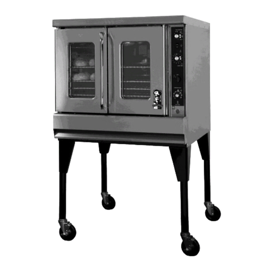
INSTRUCTION MANUAL
M
ONTAGUE
Gas
Convection Ovens
MODELS:
70, 115, R85, 2-70,
2-115 & R2-85 Series
These instructions should be read thoroughly before attempting installation.
Set up and installation should be performed by qualified installation personnel.
Keep area around appliances free and clear from combustibles.
PLEASE RETAIN THIS MANUAL
FOR FUTURE REFERENCE.
THE MONTAGUE COMPANY
1830 Stearman Avenue P.O. BOX 4954
HAYWARD,CA 94540-4954
TEL: 510/785-8822 FAX: 510/785-3342
Advertisement

Related Manuals for MONTAGUE Vectaire 70 Series


Summary of Contents for MONTAGUE Vectaire 70 Series
- Page 1 Set up and installation should be performed by qualified installation personnel. Keep area around appliances free and clear from combustibles. PLEASE RETAIN THIS MANUAL FOR FUTURE REFERENCE. THE MONTAGUE COMPANY 1830 Stearman Avenue P.O. BOX 4954 HAYWARD,CA 94540-4954 TEL: 510/785-8822 FAX: 510/785-3342...
-
Page 2: Table Of Contents
CONTENTS INSTALLATION ………. 3 MAINTENANCE ……… 21 OPERATION ………….. 11 SERVICE ……………… 26 COOKING HINTS ……. 16 IMPORTANT WARNING: Improper installation, adjustment, FOR YOUR SAFETY: alteration, service or maintenance can cause property damage, injury Do not store or use gasoline or other or death. -
Page 3: Installation
INSTALLATION Vectaire gas convection ovens are manufactured for use with the type of gas and electric supply indicated on the nameplate behind the fire box panel. The Vectaire oven is produced with the best possible material and workmanship. PROPER INSTALLATION IS ESSENTIAL FOR SAFE AND EFFICIENT TROUBLE-FREE OPERATION. - Page 4 INSTALLATION Ventilating Hood The ideal method of ventilating a convection oven is the use of a properly designed ventilat- ing hood. The hood should extend at least 6‖ beyond all sides of the oven. The hood should be connected to an adequate mechanical exhaust system. Information on the construction and installation of ventilating hoods may be obtained from the ―Standard for the Installation of Equipment for the Removal of Smoke and Grease Laden Va- pors from Commercial Cooking Equipment‖, NFPA No.
- Page 5 INSTALLATION CAUTION DO NOT OBSTRUCT THE FLOW OF COMBUSTION AND VENTILATION AIR TO THE OVEN. KEEP THE APPLIANCE AREA FREE AND CLEAR FROM COMBUSTIBLES Solid state components have a very short life span when exposed to temperatures above 185°F (85° C), therefore, certain installation precautions are necessary. The ―SE‖...
- Page 6 INSTALLATION Figure 1 Enclosed Base Modular Stand 16522-0 (Painted) or P/N 16532-8 (S/S) 4391-5 (Painted) or 4392-3 (S/S) Flue Deflector Draft Hood Figure 2...
- Page 7 INSTALLATION Installation of Rack Guides in Base -Kit No. 04651-5 (If provided See Fig. 3) 1. Set base upright and place on rack guide in position with rod extensions toward rear and through holes in back. 2. Install stop (B) behind vertical flange forming base opening. 3.
- Page 8 INSTALLATION Figure 4 Figure 5 Figure 6...
- Page 9 INSTALLATION GAS CONNECTION Before connecting oven to the gas supply line, be sure that all new piping has been cleaned and purged to prevent any foreign matter from being carried into the controls by the gas. In some cases, filters or drops are recommended. A separate gas shutoff valve must be installed upstream from the gas pressure regulator adjacent to the oven and be located in an accessi- ble area.
- Page 10 INSTALLATION Model R85 (Refer to Fig. 2, p. 4) Uncrate oven and base as near to final location as possible. Remove all packing material and accessories from oven interior. With help from at least two other people, tip the oven slowly on its side.
-
Page 11: Operation
OPERATION GAS CONTROL SYSTEM—All Models Except with Suffix ―EI‖ Lighting Turn on main gas shutoff valve and electrical service. IN THE EVENT A GAS ODOR IS DETECTED, SHUT DOWN UNITS AT MAIN SHUTOFF VALVE AND CONTACT THE LOCAL GAS COMPLANY OR GAS SUPPLIER FOR SERVICE. 1. - Page 12 OPERATION GAS CONTROL SYSTEM—Models With Suffix ―EI‖ (Equipped with electronic ignition system) Operation 1. Turn manual valve to ―ON‖ position. 2. Set thermostat to desired temperature. 3. Push toggle of Start/Reset switch to ―UP‖ position and release. The electronic pilot ignition control will automatically light the pilot and burner each time the thermostat calls for heat.
- Page 13 OPERATION Models With Suffix ―EI‖ Same as ―Standard Models‖ above except for ―START/RESET‖ switch for the electronic ignition system. Depress switch momentarily at the start of the work period. INTERMITTENT FAN OPERATION (IFO) CONTROLS (Optional) The IFO fan control cycles the fan ON for 30 seconds and OFF for 30 seconds during a variable time of 0.1 to 10 minutes of the cook period.
- Page 14 OPERATION OPERATION MOIST AIR CONTROLS & OPERATION (optional) Moist Air (Steam) Option The Moist Air option permits the operator to add steam to the oven chamber during the cooking cycle. This is desirable during baking operations for crusting purposes or to maximize growth during the initial bake period.
- Page 15 OPERATION CAUTION Never attempt to open the oven doors while the Moist Air indicator light is on, and use caution for at least 5 minutes after the light has gone out. The hot, moist air resulting from the steam generation could cause serious burns. Best performance from the Moist Air option is realized at temperatures of 300°F and above.
-
Page 16: Cooking Hints
COOKING HINTS COOKING HINTS USING A CONVECTION OVEN The convection oven is a different type of oven which offers many features and advantages to the food service operation. The operation of the oven is not difficult to understand or control. The convection oven is the sealed type whereby the combustion products are separated from the air inside the oven. - Page 17 COOKING HINTS Guide to Time and Temperature...
- Page 18 COOKING HINTS COOKING HINTS Suggestions Avoid recipes that would not be satisfactory in a regular conventional oven. Times and temperatures will vary slightly with maximum to minimum oven loads. Stagger pans in ovens as much as possible to allow the free flow of air. ...
- Page 19 COOKING HINTS ―HIT OR MISS‖ recipe mixing: Guess work in the matter of quality and quantity of ingredients frequently results in poor bakes. The following are some baking problems and their probable causes: Goods Pulled to Rear of Oven Oven not level. Pitched to rear causes dough to run to rear. ...
- Page 20 COOKING HINTS Lack of Uniformity—Same Pan Uneven loading in pan. (See uneven bakes). Faulty pans. Lack of Spring Overproofing. Incorrect temperature. Cracked Cakes Too high temperature Too fast cooling. Underdone Pie Bottoms (Advisable to bake on cookie sheet) Pastry too rich.
-
Page 21: Maintenance
MAINTENANCE MAINTENANCE CAUTION DISCONNECT POWER BEFORE CLEANING OR SERVICING. EACH OVEN SECTION HAS A SEPARATE ELECTRICAL SUPPLY CONNECTION. General Cleaning The complete oven should be given a periodic cleaning. Lint and grease suspended in the air tend to collect in air passages. Remove burner compartments access panel and clean any dirt and lint from burner primary air opening and all air passages and openings. - Page 22 MAINTENANCE MAINTENANCE Excessive spillage or crust which is allowed to build up on oven interior surfaces will seriously retard the continuous cleaning action. It should be wiped away as soon as possible with a damp cloth. Although the oven may appear clean, we recommend operating the oven at high heat for approximately two hours once every month.
- Page 23 MAINTENANCE TO REMOVE HEAT TINT: Darkened areas sometimes appear on stainless steel surfaces where the area has been subjected to excessive heat. These darkened areas are caused by thickening of the protective surface of the stainless steel and are not harmful. Heat tint can usually be removed by the foregoing, but tint which does not respond to this procedure calls for a vigorous scouring in the direction of the polish lines, using SCOTCH-BRITE scouring pads or a STAINLESS scouring pad in combination with a powdered cleanser.
- Page 24 ADJUSTMENT Main Burner While your oven has been factory adjusted, it sometimes happens that the actual operating conditions are different. Therefore, it may be necessary to make a field adjustment to secure satisfactory performance. The air adjustment should give a medium sharp flame without lifting or flashback.
- Page 25 ADJUSTMENT DOOR SWITCH ADJUSTMENT—Models With Suffix ―A‖ Door switch can only be adjusted by bending switch lever with pliers. Procedure: 1. Remove upper front trim panel for access to switch. 2. Bend switch lever with pliers so that fan will stop when door is opened between 9 and 10 inches.
-
Page 26: Service
SERVICE WHEN SERVICE IS NEEDED, CONTACT A LOCAL SERVICE COMPANY, DEALER, OR FACTORY TO PERFORM MECHANICAL MAINTENANCE AND REPAIRS. THESE IN- STRUCTIONS ARE INTENDED FOR USE BY COMPETENT SERVICE PERSONNEL. CAUTION: DISCONNECT POWER BEFORE DOING ANY SERVICE WORK. EACH OVEN SECTION HAS A SEPARATE ELECTRICAL SUPPLY CONNECTION. - Page 27 SERVICE SERVICE TO ADJUST BY-PASS (Be sure pilot flame is ignited): 1. With oven cold, turn dial counterclockwise slowly from ―Low-Stop‖ until by-pass seat just snaps on. 2. Remove dial. 3. With a screwdriver, turn ―By-Pass Adjustment Screw‖ (see sketch) counterclockwise to increase the by-pass flame to clockwise to decrease it until flame over entire burner is approximately 1/4‖...
- Page 28 SERVICE To Recalibrate 1. Remove dial from dial shaft ―B‖. 2. Turn screw ―A‖ clockwise to decrease and counterclockwise to increase the temperature. 3. 1/4 turn changes the temperature 35° 4. Replace dial on dial shaft. 5. After a calibration is made, set the dial at 350°...
- Page 29 SERVICE REMOVAL OF MAIN BURNER AND PILOT BURNER 1. Remove burner box panel for access. 2. Turn off gas supply to oven. Remove single screw at front of burner on the left side. 3. Slide main burner to the left until venturi clears orifice and pull main burner and pilot burner out far enough for access to the pilot burner mounting screws.
- Page 30 SERVICE COMBINATION SAFETY PILOT VALVE & AUTOMATIC GAS VALVE Safety Pilot Valve Section The 100% safety shutoff valve operates from millivoltage produced by a thermocouple properly heated by the pilot flame. In the event of a low, unstable pilot flame or outage, the safety valve provides complete gas shutoff.
- Page 31 SERVICE CHECKOUT PROCEDURE BEFORE LEAVING THE INSTALLATION, A COMPLETE OPERATING CYCLE SHOULD BE OBBSERVED TO SEE THAT ALL COMPONENTS ARE FUNCTIONING PROPERLY. GAS PRESSURE REGULATOR WARNING NO UNTRAINED PERSON SHOULD ATTEMPT TO MAINTAIN OT SERVICE THE GAS PRESSURE REGULATOR REMOVAL OF BURNER BOX FRONT AND BURNER BAFFLE 1.
- Page 32 SERVICE 3. Pull plate forward 1-1/4" to 1-1/2" so that motor flange clears the 10" cut out in back of oven. Then let motor drop and rest on frame. (The first time this is done, the 1/8" thick rectangular insulation pad between motor and oven back will have to be forced to fit round 10"...
- Page 33 SERVICE SERVICE MODELS WITH SUFFIX ―Z‖ Removal of Gear Panels 1. Remove burner compartment panel. 2. Remove screw from lower edge of gear panel. Pull bottom edge of panel forward so that top of panel clears upper door rod. Synchronize Oven Door 1.
- Page 34 SERVICE Adjusting Door Seal It is important that the door seal be maintained across entire door but not too tight. 1. Loosen Bolts I’D‖ 2. Doors will slide up or down. 3. Tighten up Bolts ―D‖. NOTE: If after doors are synchronized there is not enough adjustment in bolt holes ―D‖, it will be necessary to loosen Bearing ―E‖, move Gear Rack ―F‖...
- Page 35 SERVICE Electric Thermostat (Models with suffix ―E, EI‖) 1. Electric plug out. 2. Electric terminal loose. 3. Defective solenoid valve. Oven Burner Will Not Shut Off or Oven Gets Too Hot Gas Thermostat (Models with suffix ―G‖) 1. Oven thermostat out of calibration. 2.
- Page 36 SERVICE Model with Suffix ―G‖ Model with Suffix ―F‖ Intermittent Fan Operation...
- Page 37 SERVICE Model with Suffix ―E‖ — 2 speed Motor Model with Suffix ―G‖ — 2 speed Motor Model with Suffix ―E‖ — with Magnetic Starter Model with Suffix ―G‖ — with Magnetic Starter...
- Page 38 SERVICE Model with Suffix ―EI‖ — 2 Speed Motor Model with Suffix ―EI‖ — 1 Speed Motor 120V, 60 Hz, 1PH 120-240V, 60 Hz, 1PH Model with Suffix ―E‖ — 50 Hz Model with Suffix ―E‖ 480V, 60Hz, 3 PH w/ 120V Control Circuit...
- Page 39 R85 Kits Single Unit Accessory Kit - Black 29241-9 includes: Gusset Legs; Single Unit Flue Deflector; Attaching Hardware Single Unit Accessory Kit - SIS 29242-7 includes: Gusset Legs; Single Unit Flue Deflector; Attaching Hardware RD1 Double-stack Accessory and Flue Kit - Black 29243-5 includes: 6"...
- Page 41 VECTAIRE Gas Convection Oven-Horizontal Door Model 1 ..3395-2 ..Thermostat, Gas (FDO) 42 ..4562-4 ..Panel, Upper (Elec. Timer) 2 ..1024-3 ..Dial, Thermostat-Gas 43 ....... Panel. Lower 1 3 ..3499-1 ..Thermostat, Electric (KX) 44 ..4309-5 ..Panel, Upper El. Therm. (Mech. Timer) 4 ..
- Page 43 VECTAIRE Gas Convection Oven-Vertical Door Model 1 ..3395-2 ..Thermostat, Gas (FDO) 41 ..4487-3 ..Panel, Lower 2 ..1024-3 ..Dial, Thermostat—Gas 42 ....... Panel, Upper (Elec. Timer) 3 ..3499-1 ..Thermostat, Electric (KX) 43 ....... Panel. Lower 11 4 ..
- Page 44 In order to establish full compliance with Proposition 65, we attached a yellow warning label to each gas fired unit manufac- tured by the Montague Company. Carbon monoxide would not be present in concentrations that would pose a "significant risk" to the consumer when the equipment is installed, operated and maintained as follows: 1.
- Page 45 Serial No. _____________________________________________ Model No. _____________________________________________ Change No. ____________________________________________ Name & No. of Part Model No. Change No. Serial No. The Montague Company 1830 Stearman Avenue P.O. Box 4954 Hayward, CA 94540-4954 (REV. B) P/N 4520-9 1/05...
Need help?
Do you have a question about the Vectaire 70 Series and is the answer not in the manual?
Questions and answers