Advertisement
Quick Links
Advertisement

Related Manuals for Fracarro 3DG-2S2-2T


Summary of Contents for Fracarro 3DG-2S2-2T
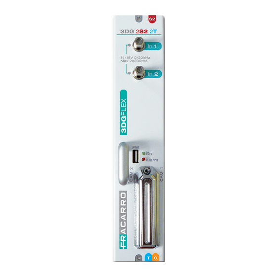
- Page 1 3DG-2S2-2T Operating instructions...
-
Page 2: Safety Warnings
• The product can only be installed by qualified personnel in compliance with local safety laws and regulations. Fracarro Radioindustrie is free from all civil and criminal responsibility due to breaches of the current legislation derived from the improper use of the product by the installer, user or third parties. -
Page 3: Product Description
PC connected to the LAN port on the control unit. Each 3DG-2S2-2T can generate 14/18V per input, 22 KHz tone and DISEqC 1.0 tone-burst to control other multiswitches, if any, or LNB and is equipped with a short-circuit protection... -
Page 4: Product Installation
3. PRODUCT INSTALLATION 3.1 PACKAGING CONTENTS All’interno dell’imballo sono contenuti i seguenti materiali: • modulo 3DG • avvertenze per la sicurezza e l’installazione del prodotto 3.2 MODULE ASSEMBLY 3.3 INSERTION AND REMOVAL OF THE CAM MODULES See the figures: To remove the CAM, press CAM insertion the corresponding button... - Page 5 After resetting, you can set the parameters again as default parameters might not meet your needs. The 3DG-2S2-2T unit is equipped with two front LEDs (red and green) which indicate the mo- dule status (i.e. ON, under alarm, under lockage, under booting or programming).
-
Page 6: Programming Instructions
5.1 BASE PROGRAMMING FROM THE STATION The 3DG-2S2-2T module can be programmed using the keyboard on the station control unit. To access the programming menu, press √ and input the user code (default is 1234). To change the 3DG-2S2-2T language enter the main menu in the control unit “LANGUAGE”,... - Page 7 Operating instructions...
- Page 8 Key: Only for module configuration in DVB-T ■ Only for module configuration in DVB-C ■...
- Page 9 Operating instructions Key: Only for module configuration in DVB-T ■ Only for module configuration in DVB-C ■...
- Page 10 INPUT Set frequency (SAT 1): DiSEqC: allows setting the DiSEqC according to the satellite (A, B, C o D). FREQ. (MHz): allows setting the extended frequency for the transponder to be received. POLARITY: to set horizontal or vertical polarity. TYPE LNB: to set the type of LNB. SYMBOL RATE: allows setting the symbol rate for the transponder to be received.
- Page 11 Operating instructions All PIDS: a function that allows enabling or deactivating the output broadcast of all the programs. (PID) contained in the selected input (in other cases, the maximum limit is 64 programs). OFF: function deactivated SAT1: selected input SAT1 SAT2: selected input SAT2 INPUT BP: selected input back panel FEC (only for modules set in DVB-T): to set the FEC (Forward Error Correction)
- Page 12 Overflow alarm: bitrate overflow alarm management. Alarm state: shows if a bitrate overflow has occurred Cancel alarm: to cancel the overflow alarm. The product is reset on the standard working conditions (the red LED is turned off) Enable: to enable (ON) or deactivate (OFF) the overflow alarm signal function (mux 2) see mux 1 Back panel: to respectively: deactivate the output signal passage on the back panel (OFF), to enable the satellite output 1 signal passage on the back panel (SAT 1), to enable...
- Page 13 Operating instructions - Monitor yes/no: to enable/deactivate the program bitrate monitoring if it has not been added to the channel list. This enables verifying whether the program has been included in the output mux or not, according to the program bitrate. - Average value: to view the program average bitrate value - Peak value: to view the program peak bitrate value.
- Page 14 IMPORTANT: to access programming from the web interface, the control unit must be outside the main menu (logo 3DGflex Fracarro shown on the display). NOTE: the web interface could vary according to the firmware release installed in the module.
- Page 15 If they are present, this screen shows the module status. The 3DG-2S2-2T module specifically shows: the symbol V, if the enabled inputs have a signal The 3DG-2S2-2T module specifically shows: the symbol V, if the enabled inputs have a signal and the receiver has locked it, the symbol <...
- Page 16 For the enablement or otherwise of the output back panel, the wording “Output BP ON” or “Output BP OFF” is shown. By clicking with the mouse on one of the present modules, the screen below opens, which shows further details about the status of the selected module: Beginning from the top, the software release and the module serial number are shown.
- Page 17 Operating instructions The receiver input parameters can be set. First of all, the input can be enabled or deactivated by flagging “enable” or otherwise, consequently from the dropdown menu select whether to set the frequency or the IF frequency. Selecting DiSEqC enables setting the DiSEqC according to the satellite (A, B, C or D). A specific section enables writing the extended frequency or in 1IF of the transponder to be received.
- Page 18 Besides indications as to whether the CAM module is present or not, there is a table with a list of the programs in the transponder locked to the relative input. Besides the program name, we can see if the program is free to air < >...
- Page 19 Operating instructions The following screen opens by clicking on “Common interface menu”: Information is given about the CAM module, the Smartcard and the last CAM software release can also be downloaded. The menu above refers to the input CAM and in this case the menu headings refer to that specific type of CAM.
- Page 20 In this section the input can be enabled for the back panel signal in the module coming from the output back panel of the module in the previous position. The right hand section also displays certain information about the input signal, including: if it is locked or not, the network name, network ID, original network ID and the transport stream ID.
- Page 21 Operating instructions Here the main parameters for the output mux can be set. In particular, the first selection from the dropdown menu enables choosing the modulator frequency: by frequency or by channel. After which we can set: the bandwidth of the output channel, the frequency or the channel/ country, the RF level (0-15), the FEC (1/2 ,2/3, 3/4, 5/6, 7/8), the guard interval (1/4,1/8,1/16,1/32), the constellation (QPSK,16QAM and 64QAM), the number of carriers (8K, 2K), the spectrum (normal, inverted), the single tone, which enables using a single output tone to facilitate...
- Page 22 In the configuration menu click on the mouse to select the output back panel to open the following screen, where the output back panel can be enabled or deactivated for the signal coming from: SAT 1, SAT 2, Back panel. In the green option bar at the top select “Configuration”...
- Page 23 Operating instructions of the two output muxes, the box is automatically flagged and the relative band is displayed. Initially the lines in the other 2 tables for the output muxes are empty, and can be filled with the programs chosen from the input program list using the drag and drop function. To do this, click with the left key on the mouse over the selected program in the input program list and keep it pressed and drag the program to the table in the required output mux and then release the key.
- Page 24 important for the LCN to function correctly, and they must be inserted consistently with the same parameters inserted in the connected decoders and televisions. By clicking on the program properties key < > the following screen opens: In the first table, by directly writing in the spaces, certain program parameters can be changed including: the name, the provider, the SID, the PMT PID.
- Page 25 Operating instructions Important: For the programming to be correct the following sequence must be respected: 1. Add programs to the output MUX. 2. Set the program positions. 3. Set the MUX advanced configurations. 4. Set the properties of the single program. N.B.
- Page 26 By clicking on the advanced configuration key, the following screen opens: Where the following parameters can be set: - Set the “ALL PIDS” function to enable or deactivate the output broadcast of all the programs (PID) in the selected input (SAT 1, SAT 2 or back panel). In this case, the parameters listed below can no longer be set as the original ones are maintained.
- Page 27 Operating instructions Certain advanced signal parameters can then be viewed, including: the Original Network ID, the Network ID and the Private Data Specifier Descriptor. Other parameters can also be set (by writing the new number in the space) including: Transport Stream ID, Network Name, Cell ID, NIT version and SDT version.
- Page 28 To enable this function, select the control unit from “Home” and then “Monitoring” and “Configuration” and the following screen opens: First of all in the “Monitoring settings” section enable the required function. The other parameters are then set in the other sections, in particular those regarding the SMTP server, the port, the email addressee, etc.
- Page 29 Operating instructions In the Home page, select any of the modules, and in the green option bar at the top select. “Configuration”->“Monitoring” -> “Status” the following screen opens: In this screen the time interval and number of attempts can be set for monitoring the parameters. Below just some of the monitored parameters are shown.
- Page 30 The others can be identified in the various menus: by pointing the mouse over the parameters a question mark appears and by clicking on the right hand key on the mouse the following type of screen opens: To monitor the program decrypt, it should be enabled from this general menu and then, if there are problems, from the menu for each program (enabled from the input program list menu <...
- Page 31 Operating instructions In the green option bar at the top select “operations” -> “copy” to open the following screen: In the dropdown menu the module can be selected where the configuration is copied from and the module where it should be copied to. In the green option bar at the top select “operations”...
- Page 32 In the green option bar at the top select “operations” -> “load configuration”-> “from file”/”from USB drive” to open the following screen, for example: In this screen you can select the module where the configuration, which has been saved in a PC file or a USB drive, should be loaded to.
- Page 33 If the programs are programmed singularly (PID) for them to be available on output, the indications given below must be scrupulously followed. Programming and setting the modulation parameters for the 3DG-2S2-2T module must be done very carefully in the manner described below. In particular, the total output program bitrate for each mux must be lower than the maximum limit defined by the modulation parameters.
- Page 34 Guard interval DVB-T 64-QAM 1/16 1/32 14,929 16,588 17,564 18,096 19,906 22,118 23,419 24,128 22,394 24,882 26,346 27,144 24,882 27,647 29,273 30,160 26,126 29,029 30,737 31,668 m-QAM DVB-C 7,373 9,216 11,059 12,902 14,745 18,800 23,500 28,200 32,900 37,600 22,118 27,647 33,176 38,706 44,235...
- Page 35 Operating instructions the distributed programs, i.e. with static bitrate (A) or dynamic bitrate (B). Therefore information should be obtained beforehand, using stats that can be found in the web, alternatively (but which may not be sufficient) the supplied bitrates must be monitored for a few minutes from the web interface or the keypad on the station control unit.
- Page 36 5.4 FIRMWARE UPGRADE The 3DG-2S2-2T module can be upgraded directly and remotely via the web. The direct upgrade procedure involves loading the firmware, previously saved on a USB drive, directly on the module through its USB port (see the programming flowchart).
- Page 37 Operating instructions The following screen opens: Select the correct firmware file and wait for it to load, after which the modules can be selected that need upgrading:...
- Page 38 Press on each module to select the partitions to be upgraded, as listed in the following screen: If a general upgrade is required, this operation is not required, just press on “Upgrade modules” in the previous screen. When the upgrade has been launched, the following screen opens showing the procedure progress for each module and relative partitions:...
- Page 39 Results” as shown in the following screen: When the module is turned on for the first time, check the software release is the most recent one available in the fracarro.com website. Periodically check to see if new releases have been published.
-
Page 40: Technical Specifications
6. TECHNICAL SPECIFICATIONS INPUT SIGNAL Number of inputs 2 inputs on type F female connectors Standard modulation DVB-S2, DVB-S Input frequency 950 to 2150MHz Input frequency step 1MHz Input frequency correction offset (AFC) ±5MHz Input level 45 to 85dBμV Input return loss Input impedance 75Ω... -
Page 41: Compliance With European Directives
Operating instructions 7. COMPLIANCE WITH EUROPEAN DIRECTIVES Fracarro Radioindustrie SpA declares that the product complies with the requisites of the following European directives: EN 50083-2, EN 60065 and therefore the product complies with the requisites of the following harmonized standards (including all applicable modifications):... - Page 43 Note...
- Page 44 Garantito da/ Guaranteed by/ Garanti par/ Garantizado por/ Garantido por/ Garantiert durch/ Zajamčena od/ Garantirano od/ Garantovano od/ Gwarantowane przez / Εγγυημένο από/ Гарантировано Fracarro Radioindustrie S.p.A., Via Cazzaro n. 3, 31033 Castelfranco Veneto (Tv) – Italy supportotecnico@fracarro.com Fracarro Radioindustrie S.p.A.
Need help?
Do you have a question about the 3DG-2S2-2T and is the answer not in the manual?
Questions and answers