Allen-Bradley CompactLogix 1769-L32E Installation Instructions Manual
Hide thumbs
Also See for CompactLogix 1769-L32E:
- User manual (148 pages) ,
- Programming manual (90 pages) ,
- Programming manual (36 pages)
Table of Contents
Advertisement
Quick Links
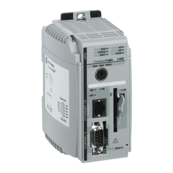
1769-L32E, 1769-L35E CompactLogix Controller
Catalog Numbers 1769-L32E, 1769-L35E
Topic
About This Publication
Important User Information
North American Hazardous Location Approval
Environment and Enclosure
Before You Begin
Prevent Electrostatic Discharge
Connect the 1769-BA Battery
Install a 1784-CF64 or 1784-CF128 Industrial CompactFlash Card
(optional)
Assemble the System
Mount the System
Make RS-232 Connections to the Controller
Make Ethernet Connections to the Controller
Load the Controller Firmware
Select the Controller's Operating Mode
Make Ethernet Connections to the Controller
Load the Controller Firmware
Select the Controller's Operating Mode
Controller Status Indicators
RS-232 Serial Port Status Indicators (Channel 0 and 1)
Installation Instructions
Page
2
3
4
5
6
7
7
9
9
11
15
18
25
30
18
25
30
31
33
Publication
1769-IN020-C-EN-P - July 2007
Advertisement
Table of Contents

Related Manuals for Allen-Bradley CompactLogix 1769-L32E


Summary of Contents for Allen-Bradley CompactLogix 1769-L32E
- Page 1 Installation Instructions 1769-L32E, 1769-L35E CompactLogix Controller Catalog Numbers 1769-L32E, 1769-L35E Topic Page About This Publication Important User Information North American Hazardous Location Approval Environment and Enclosure Before You Begin Prevent Electrostatic Discharge Connect the 1769-BA Battery Install a 1784-CF64 or 1784-CF128 Industrial CompactFlash Card (optional) Assemble the System Mount the System...
-
Page 2: About This Publication
2 1769-L32E, 1769-L35E CompactLogix Controller Topic Page CompactFlash Card Status Indicator Module Status (MS) indicator Additional Resources About This Publication Use this document as a guide to install the CompactLogix controller. Publication 1769-IN020-C-EN-P - July 2007... -
Page 3: Important User Information
1769-L32E, 1769-L35E CompactLogix Controller 3 Important User Information Solid state equipment has operational characteristics differing from those of electromechanical equipment. Safety Guidelines for the Application, Installation and Maintenance of Solid State Controls (publication SGI-1.1 available from your local Rockwell Automation sales office or online at http://literature.rockwellautomation.com) describes some important differences between solid state equipment and hard-wired electromechanical devices. -
Page 4: North American Hazardous Location Approval
4 1769-L32E, 1769-L35E CompactLogix Controller North American Hazardous Location Approval The following information applies when Informations sur l'utilisation de cet équipement en operating this equipment in hazardous environnements dangereux. locations. Products marked “CL I, DIV 2, GP A, B, C, D” are Les produits marqués “CL I, DIV 2, GP A, B, C, D”... -
Page 5: Environment And Enclosure
1769-L32E, 1769-L35E CompactLogix Controller 5 Environment and Enclosure This equipment is intended for use in a Pollution Degree 2 industrial environment, in ATTENTION overvoltage Category II applications (as defined in IEC publication 60664-1), at altitudes up to 2000 meters (6562 feet) without derating. This equipment is considered Group 1, Class A industrial equipment according to IEC/CISPR Publication 11. -
Page 6: Before You Begin
6 1769-L32E, 1769-L35E CompactLogix Controller Before You Begin Consider the following when planning your CompactLogix system: • The CompactLogix controller is always the leftmost module in the system. • The controller must be located within four modules of the system power supply. Some I/O modules may be located up to eight modules away from the power supply. -
Page 7: Prevent Electrostatic Discharge
1769-L32E, 1769-L35E CompactLogix Controller 7 Prevent Electrostatic Discharge Follow these guidelines to prevent electrostatic damage. This equipment is sensitive to electrostatic discharge, which can cause internal ATTENTION damage and affect normal operation. Follow these guidelines when you handle this equipment: •Touch a grounded object to discharge potential static. - Page 8 8 1769-L32E, 1769-L35E CompactLogix Controller 1. Remove the battery door by sliding it forward. Do not remove the plastic insulation covering the battery. The insulation is necessary IMPORTANT to protect the battery contacts. 2. Insert the battery connector into the connector port. The connector is keyed to be installed with the correct polarity.
-
Page 9: Assemble The System
1769-L32E, 1769-L35E CompactLogix Controller 9 Install a 1784-CF64 or 1784-CF128 Industrial CompactFlash Card (optional) ATTENTION Do not remove the CompactFlash card while the controller is reading from or writing to the card, as indicated by a flashing green CF status indicator. This could corrupt the data on the card or in the controller, as well as corrupt the latest firmware in the controller. - Page 10 10 1769-L32E, 1769-L35E CompactLogix Controller Grounding Considerations on page 12 or DIN Rail Mounting on page The CompactLogix controller is not designed for removal and insertion under power. WARNING If you insert or remove the module while backplane power is on, an electrical arc can occur.
-
Page 11: Mount The System
1769-L32E, 1769-L35E CompactLogix Controller 11 6. Move the module’s bus lever fully to the left (D) until it clicks, being sure it is locked firmly in place. ATTENTION When attaching the controller, power supply, and I/O modules, make sure the bus connectors are securely locked together to be sure of proper electrical connection. -
Page 12: System Dimensions
12 1769-L32E, 1769-L35E CompactLogix Controller System Dimensions 67.5 mm 70 mm 35 mm (2.68 in.) (2.76 in.) (1.38 in.) 15 mm 52.5 mm (.59 in.) (2.06 in.) 132 mm (5.20 in.) 118 mm (4.65 in.) 52.5 mm 35 mm 35 mm 35 mm 35 mm (2.07 in.) -
Page 13: Panel Mounting
1769-L32E, 1769-L35E CompactLogix Controller 13 Panel Mounting Mount the controller to a panel by using two screws per module. Use M4 or #8 panhead screws. Mounting screws are required on every module. This procedure lets you use the assembled modules as a template for drilling holes in the panel. -
Page 14: Din Rail Mounting
14 1769-L32E, 1769-L35E CompactLogix Controller 6. Attach the modules to the panel by using the mounting screws. If you are mounting more modules, mount only the last one of this group and put the others aside. This reduces remounting time when you are drilling and tapping the next group of modules. -
Page 15: Make Rs-232 Connections To The Controller
1769-L32E, 1769-L35E CompactLogix Controller 15 Make RS-232 Connections to the Controller Connect the 9-pin female end of the serial cable to the serial port of the controller. If you connect or disconnect the serial cable with power applied to this module or the WARNING serial device on the other end of the cable, an electrical arc can occur. -
Page 16: Default Serial Configuration
16 1769-L32E, 1769-L35E CompactLogix Controller Default Serial Configuration Channel 0 and Channel 1 (both serial ports) have the following default communication configuration. Parameter Default Protocol DF1 full-duplex Communication Rate 19.2 Kbps Parity None Station Address Control Lines No Handshaking Error Detection Embedded Responses Auto Detect Duplicate Packet (Message) Detect... - Page 17 1769-L32E, 1769-L35E CompactLogix Controller 17 Using the Channel 0 Default Communication Push Button The Channel 0 default communication push button is located on the front of the controller in the lower right corner as shown in the illustration. Use the Channel 0 default communication push button to change from the user-defined communication configuration to the default...
-
Page 18: Make Ethernet Connections To The Controller
18 1769-L32E, 1769-L35E CompactLogix Controller Make Ethernet Connections to the Controller The 1769-L32E and 1769-L35E controllers ship with the BOOTP utility enabled. You must assign an IP address to the Ethernet port in order for the controller to communicate over an EtherNet/IP network. If you connect or disconnect the communications cable with power applied to this module WARNING or any device on the network, an electrical arc can occur. - Page 19 1769-L32E, 1769-L35E CompactLogix Controller 19 Assigning an IP address You can set the IP address using any of these utilities: • Rockwell BOOTP Utility (available with RSLinx and RSLogix 5000 software) • RSLinx software • RSLogix 5000 software Use BOOTP to set the IP address The BOOTP utility is a standalone program that is located in one of the following directories: •...
-
Page 20: Enter The Ip Address
20 1769-L32E, 1769-L35E CompactLogix Controller In the BOOTP Request History dialog you see the hardware addresses of devices issuing BOOTP requests. 5. Double-click on the hardware address of the device you want to configure. The hardware address is on the sticker located on the left-side circuit board of the controller next to the battery. - Page 21 1769-L32E, 1769-L35E CompactLogix Controller 21 7. Click Ok. 8. To permanently assign this configuration to the device, highlight the device and click Disable BOOTP/DHCP. When power is recycled, the device uses the configuration you assigned and does not issue a BootP request. Use RSLinx software to set the IP address You can use RSLinx software, version 2.41 or later, to set the IP address.
- Page 22 22 1769-L32E, 1769-L35E CompactLogix Controller 5. Right-click the Ethernet port (not the controller) and select Module Configuration 6. Select the Port Configuration tab. Publication 1769-IN020-C-EN-P - July 2007...
- Page 23 1769-L32E, 1769-L35E CompactLogix Controller 23 7. Click the appropriate radio button to choose the Status Network Configuration type. 8. Enter the IP address, network (subnet) mask, and gateway address (if needed). Use RSLogix 5000 software to set the IP address You can use RSLogix software to set the IP address.
- Page 24 24 1769-L32E, 1769-L35E CompactLogix Controller 3. Start RSLogix 5000 software. In the Controller Organizer, select properties for the Ethernet port. 4. Choose the Port Configuration tab. 5. Specify the IP address. 6. Click Apply. 7. Click Ok. This sets the IP address in the hardware. This IP address should be the same IP address you assigned under the General tab.
-
Page 25: Load The Controller Firmware
1769-L32E, 1769-L35E CompactLogix Controller 25 Install the Appropriate EDS Files If you have RSLinx software, version 2.42 or later, the most current EDS files were installed with the software. If you are using an earlier version of RSLinx software, you might need to install EDS files. You need EDS files for these devices: •... - Page 26 26 1769-L32E, 1769-L35E CompactLogix Controller The firmware is available with RSLogix 5000 software or you can download it from the support website. Go to http://support.rockwellautomation.com. Follow these steps to download firmware from the support website. 1. In the left column (frame), click Technical Support. 2.
- Page 27 1769-L32E, 1769-L35E CompactLogix Controller 27 Use the ControlFlash Utility to Load Firmware You can use the ControlFlash utility to load firmware through a serial connection. 1. Make sure the appropriate network connection is made before starting. 2. Start the ControlFlash utility. 3.
- Page 28 28 1769-L32E, 1769-L35E CompactLogix Controller Use AutoFlash to Load Firmware You can use AutoFlash to load firmware through a serial connection. 1. Make sure the appropriate network connection is made before starting. 2. Use RSLogix 5000 programming software to create a controller project.
- Page 29 1769-L32E, 1769-L35E CompactLogix Controller 29 Use a CompactFlash Card to Load Firmware If you have an existing controller that is already configured and has firmware loaded, you can store the current controller user program and firmware on the CompactFlash card and use that card to update other controllers.
-
Page 30: Select The Controller's Operating Mode
30 1769-L32E, 1769-L35E CompactLogix Controller Select the Controller’s Operating Mode Use the keyswitch on the front panel of the controller to determine the controller’s operating mode. Keyswitch Description Position •Upload projects. •Run the program and enable outputs. •You cannot create or delete tasks, programs, or routines. You cannot create or delete tags or edit online while the keyswitch is in the Run position. -
Page 31: Controller Status Indicators
1769-L32E, 1769-L35E CompactLogix Controller 31 Controller Status Indicators Indicator Status Description The controller is in Program or Test mode. Solid green The controller is in Run mode. •No tags contain I/O force values. FORCE •I/O forces are inactive (disabled). •I/O forces are active (enabled). Solid amber •I/O force values may or may not exist. -
Page 32: Publication 1769-In020-C-En-P - July
32 1769-L32E, 1769-L35E CompactLogix Controller Indicator Status Description No power is applied. Flashing red If the controller is new, the controller requires a firmware update. If the controller is not new, a major fault occurred. To clear the fault, do one of the following: •Turn the keyswitch from Prog to Run to Prog. -
Page 33: Rs-232 Serial Port Status Indicators (Channel 0 And 1)
1769-L32E, 1769-L35E CompactLogix Controller 33 RS-232 Serial Port Status Indicators (Channel 0 and 1) Indicator Status Description DCH0 Channel 0 is configured differently than the default serial configuration. Solid green Channel 0 has the default serial configuration. No RS-232 activity. Flashing green RS-232 activity. -
Page 34: Module Status (Ms) Indicator
34 1769-L32E, 1769-L35E CompactLogix Controller Module Status (MS) indicator Condition Status Indicates Recommended Action No power The controller does not have Check the controller power supply. power. Flashing green Standby The port does not have an IP Verify that the BOOTP server is address and is operating in running. -
Page 35: Network Status (Ns) Indicator
1769-L32E, 1769-L35E CompactLogix Controller 35 Network Status (NS) indicator Condition Status Indicates Recommended Action Not initialized The port does not have an IP Verify that the BOOTP server is address and is operating in running. BOOTP mode. Flashing green No CIP The port has an IP address, Normal operation if no connections... -
Page 36: Specifications
36 1769-L32E, 1769-L35E CompactLogix Controller Specifications CompactLogix Controller - 1769-L32E, 1769-L35E Attribute Value Communication ports CH0 - RS-232 CH1 - RS-232 RS-232 RS-232 DF1, DH-485, ASCII DF1, DH-485 fully isolated non-isolated 38.4 Kbps max 38.4 Kbps max User memory 512 KB Nonvolatile memory 1784-CF64 or 1784-CF128 CompactFlash card Number of I/O modules, max... -
Page 37: Environmental Specifications
1769-L32E, 1769-L35E CompactLogix Controller 37 Environmental Specifications Attribute Value Operational temperature 0...60 °C (32...+140 °F) IEC 60068-2-1 (Test Ad, Operating Cold) IEC 60068-2-2 (Test Bd, Operating Dry Heat) IEC 60068-2-14 (Test Nb, Operating Thermal Shock) Storage temperature -40... +85 °C (-40...+185 °F) IEC 60068-2-1 (Test Ab, Unpackaged Nonoperating Cold) IEC 60068-2-2 (Test Bb, Unpackaged Nonoperating... - Page 38 38 1769-L32E, 1769-L35E CompactLogix Controller Certifications Value Certifications (when product is marked) c-UL-us UL Listed Industrial Control Equipment, certified for US and Canada. See UL File E65584. UL Listed for Class I, Division 2 Group A,B,C,D Hazardous Locations, certified for U.S. and Canada. See UL File E194810. European Union 89/336/EEC EMC Directive, compliant with: •...
-
Page 39: Additional Resources
CompactLogix System User Manual, publication Planning, mounting, wiring, and troubleshooting 1769-UM0011 your CompactLogix system Industrial Automation Wiring and Grounding Grounding and wiring Allen-Bradley Guidelines, publication 1770-4.1 programmable controllers National Electrical Code - Published by the National Wire sizes and types for grounding electrical Fire Protection Association of Boston, MA. -
Page 40: Rockwell Automation Support
Outside United States Please contact your local Rockwell Automation representative for return procedure. Allen-Bradley, CompactLogix, ControlFlash, Rockwell Automation, RSLinx, RSLogix 5000, and TechConnect are trademarks of Rockwell Automation, Inc. Trademarks not belonging to Rockwell Automation are property of their respective companies.
Need help?
Do you have a question about the CompactLogix 1769-L32E and is the answer not in the manual?
Questions and answers