Table of Contents
Advertisement
Quick Links
Advertisement
Table of Contents

Subscribe to Our Youtube Channel
Related Manuals for OneProd FALCON


Summary of Contents for OneProd FALCON
- Page 1 FALCON USER MANUAL...
- Page 2 Brand of ACOEM...
- Page 3 FALCON USER MANUAL DOC3105 – December 2014 F Document reference: Name: FALCON USER MANUAL Firmware versions: FW 1.10 www.acoemgroup.com support@acoemgroup.com Copyright © 2014, 01dB-Metravib SAS This document is the property of 01dB-Metravib SAS. Any dissemination, copying or publicising of this document, in whole or in part, is prohibited without the owner’s written authorisation.
-
Page 4: Table Of Contents
TABLE OF CONTENT CHAPTER 1. General presentation ...................... 7 Introduction ..........................7 Safety instructions........................7 List of symbols and warning on the instrument ..............8 List of symbols and warning on WLS ..................8 Laser ............................8 Electric connections ....................... 9 First power-up ........................ - Page 5 Create a new measurement on a group of point in Off-route ......... 53 3.7.5 Modify a measurement on a group of points in Off-route ..........53 3.7.6 How to import templates in FALCON................60 3.7.7 Download OFF_ROUTE measurements to the PC ............60 CHAPTER 4.
- Page 6 4.13.1 Picture and comment ...................... 74 4.13.2 Generate report....................... 74 4.13.3 Customized report ......................74 CHAPTER 5. Maintenance ......................... 75 RESET ..........................75 Cleaning ..........................75 Calibration ..........................75 Backup of instrument memory ..................... 75 Instrument firmware update ....................75 WLS sensor firmware update....................
-
Page 7: Chapter 1. General Presentation
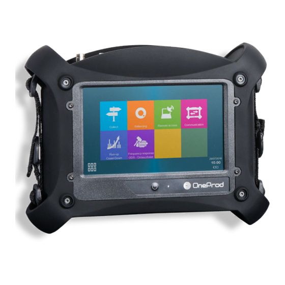
FALCON is the new generation of portable data collectors for condition monitoring, vibration analysis and balancing. Designed to meet industrial requirements for enhancing productivity, FALCON is a portable multichannel instrument coming along with a large touchscreen, a 3-axis wireless sensor and numerous accessories. -
Page 8: List Of Symbols And Warning On The Instrument
Laser maintenance: the laser does not need maintenance or adjustment excluding cleaning the glass with a cotton swab. Always shut off completely the device Falcon before this operation. Caution--use of controls or adjustments or performance of procedures other than those specified... -
Page 9: Electric Connections
1.6 E LECTRIC CONNECTIONS All external circuits connected to the instrument must be non-hazardous voltage sources and be energy limited as explained in sections 6.3 and 9.4 of the IEC61010-1 standard Do not exceed maximum input voltage on the A/B/C/D connectors: maximum input voltage ±24 V DC, ±24 V AC peak. -
Page 10: User Interface
1.8 U SER INTERFACE FALCON starts on its “Home screen”. It is a touch screen and a simple pressure on it gives access to the application modules installed on the instrument and to 2 side panels: Access to application modules... -
Page 11: Connectors E To I Behind The Trapdoor
1.9.2 Connectors E to I behind the trapdoor Those connectors are behind a trapdoor. It must remain close in industrial environment to preserve the IP65 protection. Use those connectors only in office environment. Connector E: Power supply input Connector F: Ethernet RJ45 ... -
Page 12: Wls Sensor
1.11 WLS S ENSOR FALCON can be used with a wireless triaxial accelerometer (WLS Sensor). This chapter described how to use FALCON with this sensor. 1.11.1 WLS sensor battery Use the USB cable and charger supplied with the sensor. The connector is protected by the rubber cap on the top of the sensor. -
Page 13: Wls: Led Indication
1.11.4 WLS: LED indication Red LED Blue LED Significance ——— WLS connected Charge in progress (LED brightness = 50%) to the charger ━━━━ Charge completed (LED brightness = 100%) - - - - - Charge error ——— Switch on (< 10 s) Start in progress ———... -
Page 14: Data Exchange With Pc
Note: the first 3 numbers must be the same (192.168.1) and the last one different from that of the PC (10 ≠ 12) Mask = 255.255.255.0 Once the setting is done, to access the data use FALCON IP address, e.g., in the Explorer type “\\192.168.1.10\Data”. PC- FALCON connection through LAN Network: On PC: Setup Network ... -
Page 15: Using Wi-Fi
Set the IP address, e.g., 192.168.1.14 Mask: 255.255.255.0 Scan Wi-Fi networks and select FALCON SSID. Once the setting is done, to access the data use FALCON IP address, e.g., in the Explorer type “\\192.168.1.16\Data”. Direct Wi-Fi connection PC- FALCON-WLS setting: On FALCON: ... - Page 16 Wi-Fi LAN connection PC- FALCON setting without WLS sensor: Note: WLS sensor cannot be used simultaneously with this mode. On FALCON: Setting > Network > Wi-Fi part Enabled: Yes Adhoc: No Save the setting Setting >...
-
Page 17: Status Indications
1.13 S TATUS INDICATIONS 1.13.1 Status summary The status is indicated at the bottom of the right hand side of the screen General status Date and time Battery level of the instrument During analogic measurement Input overload indication in percentage of time. Sensor integrity indicator ... -
Page 18: Shortcuts Panel
1.14 S HORTCUTS PANEL From any screen, button opens the Shortcuts panel. It gives direct access to a group of functions. The list of accessible functions depends of the current screen. 1.14.1 Photo From the Collect module, measurement list screen: take an inspection picture ... -
Page 19: Text Note
1.14.2 Text note From Collect module, measurement list screen: input text inspection note directly from the keyboard or from a list of predefined notes. The list of predefined notes is only available if this list is created in PC database ( in XPR menu “Libraries/Predefined notes”) ... -
Page 20: Vocal Note
Make sure you set the volume to a low level before starting to listen Play: listen to the comment For this function, you must have the optional 3.5 mm jack adapter on connector D (ref: CPC1229000 - FALCON ECTD-JACKF). 1.14.5 Barcode... -
Page 21: Pyrometer
2 times. Use to return to the initial frequency. 1.14.9 Screenshot From anywhere, you can save a screen copy. Images are stored in folder “Screenshots”. Connect your PC to FALCON to copy them (see § 1.12). Brand of ACOEM... -
Page 22: Settings
1.14.10 Settings See CHAPTER 2. 1.14.11 Home From anywhere you can go directly to the home screen. Brand of ACOEM... -
Page 23: Battery Management
1.15.2 Battery replacement Safety instructions: Do not use batteries other than type PIL1133 provided for FALCON and identified as 01dB Metravib WILPA 2344A Do not open or disassemble the battery pack. The pack includes protections and an assembly essential for the safety that should be changed in no case. - Page 24 Replacement instructions: Remove the battery: Unscrew the 2 screws of the battery trapdoor. Screws Screws Remove the connector by gently pulling the two cables. It should come off easily. In the case of an abnormal resistance, do not force and contact our after-sales service.
-
Page 25: Remote Display & Control Function
Install Real VNC Viewer ® on the PC FALCON must be first networked by Ethernet (see § 1.12.3) or by Wi-Fi (see § 1.12.4) with the PC To work also with WLS Sensor, use the ‘Direct Wi-Fi connection PC- FALCON-WLS setting’ configuration. -
Page 26: Chapter 2. General Setup
CHAPTER 2. ENERAL SETUP Access: Shortcuts panel > Settings 2.1 C OLLECT Possibility to protect* the modification of some route data: sensor position pictogram, location or point picture, barcode, rotation speed for measurement done by tachometer Possibility to protect* the functions ‘Delete’ and ‘Reset’ for routes not downloaded. ... -
Page 27: Wireless Sensor
Check if FALCON is set to work with a WLS sensor: Shortcuts > Setting > > Accelerometer link = Wireless Check if the serial number of the sensor is that declared in FALCON Shortcuts > Setting > Wireless sensor ... -
Page 28: Tachometer
2.4 T ACHOMETER First tab: Tachometer setup Adjustment of tachometer parameters: Input range: select the range according to the tachometer signal : +/-10V, 0/-24V, 0/+24V Coupling: DC: default setting AC: a 0.3Hz high-pass filter is applied. This can be used if the DC component of the signal is changing during measurement (for example: signal from a proximity probe during run-up / coast-down). -
Page 29: Camera
2.6 C AMERA Set the access to the barcode reader and the camera. The access to the camera can be protected by password (The protection is applied if you define a password on the last line of Settings > About). 2.7 T OUCHSCREEN ... -
Page 30: Date - Language
– 2.9 D LANGUAGE Input of: Date: format must be DD/MM/YYYY Time: format must be HH:MM Time zone: select your time zone in the list Daylight saving: Yes or No Language: select in the list ... -
Page 31: Data Management
USB memory stick format must be FAT32, NTFS format is not accepted. It is always possible to reformat it to FAT32 Connect the system to its power supply. Plug the USB memory key in FALCON connector G. Shortcuts > Setting > Update firmware ... -
Page 32: Calibration
2.14 C ALIBRATION This screen gives information on the calibration of each channel. Sensitivity can only be calibrated by authorised personnel. ‘Offset calibration’ can be used to improve the accuracy of DC measurements. An internal function Note: for this operation, ambient temperature must be between 20 and 25°C. 2.15 B ATTERY MANAGEMENT ... -
Page 33: Chapter 3. Collector Module
CHAPTER 3. OLLECTOR MODULE 3.1 I NTRODUCTION The Collect module is used to run measurement programs loaded from NEST Predictive Maintenance Software. These measurement programs are commonly called Routes. Once the measurements are performed, data are downloaded to the PC for post-processing and storage in the database. There are 2 levels of functions: ... -
Page 34: Module Organisation
3.2 M ODULE ORGANISATION Acquisition: see § 3.5.2 Route list: see § 3.4 Diagnosis: see § 3.5.4 Measurement list: see § 3.5 Measurement display: see § 3.5.3 Route exploration: see § 3.5.7 Brand of ACOEM... -
Page 35: Send A Route To The Instrument
“Collector” tab: Select “Direct transfer” and the type of connection: USB: if you connect FALCON connector H with a USB port of the PC. The PC automatically selects the connected instrument and creates it in the list if necessary. -
Page 36: Route List Screen
Directly in the folder “Import” of the instrument memory (see § 6.1) On FALCON: Go to “Collect” module If you are using a USB memory stick, insert it in the port G behind the trapdoor Click on Import Select the route to import. -
Page 37: Measurement List Screen
Reset: Reset all the measurement of the group of points. Routes: Return to the list of routes. For “OFF_ROUTE” route, with a FALCON including the Expert Offroute option: Access to OFF_ROUTE additional functions (See § 3.7) Delete: delete the selected measurement. The last one cannot be deleted. - Page 38 Functions of the screen using the shortcuts Inspection picture: see § 3.5.5. Inspection note: see § 3.5.5. Inspection vocal note: see § 3.5.5. Point identification with QRcode: see § 1.14.5. Listen sensor signal: see § 1.14.6. Use the pyrometer for temperature measurement: see § 3.5.6. Use the stroboscope for rotation speed measurement: see §...
-
Page 39: Header Description
To set it click on and select the sensor pictogram corresponding to the position of the sensor on the bearing. For WLS sensor, the X axis is marked by ACOEM or ONEPROD logo and a point at the base of the sensor. - Page 40 For a single-axis measurement, a pictogram is displayed for information: For horizontal shaft: Axial (A) , Horizontal (H) , Vertical (V) Radial oblique For vertical shaft: Axial (A) , Radial main (//) Radial perpendicular (P or ) **** Sensor position picture: it is possible to replace the pictogram by a picture of the sensor. ...
-
Page 41: Acquisition
3.5.2 Acquisition The instrument takes in one shot all measurements with the same input type for all the points grouped together. The channel association rules are explained in § 3.5.8. Progress bar: During the acquisition there is a succession of 2 progress bars: ... -
Page 42: See Measurements
3.5.3 See measurements This function displays the result of the selected measurement. If acquisition is not yet performed, it displays directly the live values. There are 3 types of display: Overall level Spectrum Time-wave Each one is available for 1, 2, 3 or 4 channels. For spectrum and time-wave, a first click on a curve selects it as the current one, a 2 click sets a cursor. - Page 43 Select active cursor, central frequency or side band . Indications: At the bottom: central frequency and distance At the top: amplitude at the central frequency Zoom +: apply a zoom factor 2 around the cursor position. Zoom -: return back to previous zoom factor Setting display: change the setting of the display: Scale: linear, logarithmic or dB (for spectrum display only) Framing:...
-
Page 44: Run Automatic Diagnosis
3.5.4 Run automatic diagnosis This function gives directly the machine diagnosis after your measurement. This function needs that the machine is created with NEST machine setup in “Automatic diagnosis” mode and that the instrument is equipped with the “Diagnosis” option. The diagnosis information is: ... -
Page 45: Inspection Information
3.5.5 Inspection information Functions of the screen using the shortcuts: It is possible to add inspection information using functions accessible through the shortcuts panel: Inspection picture: see also § 1.14.1. The pictures are downloaded as attached to the measurement date of the machine and visible in the NEST Expertise REPORT or in XPR “Measurement information”... -
Page 46: Explore The Route
3.5.7 Explore the route This function shows the contents of the route. Two modes are available: List mode: to see the machines of the route or the points of a machine in the order of measurement. Map mode: to see machines and sub-location positioned on the picture of their location or the point positioned on the picture of their machine in a simailar way as NEST machine supervision. - Page 47 Following functions are only accessible in “OFF_ROUTE” route (See § 3.7) Delete: delete the selected machine. Rename: Change the name of the selected machine. Access to OFF_ROUTE additional functions. This function is in List mode only. Create a new machine using a point template: see § 3.7.3 Copy selected machine to the clipboard.
-
Page 48: Channel Organisation
3.5.8 Channel organisation It is possible to use FALCON with WLS sensor or with 1 to 4 wired inputs. The point to channel association depends on: Instrument setting: see § 2.2. Wired channel number: Single or Multi Accelerometer link: Wire or Wireless (WLS sensor) ... - Page 49 The rules are the following: WLS Sensor (Accelerometer link = Wireless) Measurement input type = Accelerometer IEPE or Accelerometer AC Measurement channel number = Multi Configuration of the points compatible with tri-axial measurement: point-channel association is done according to the sensor position pictogram. ...
-
Page 50: Upload A Measurements To Nest
“Collector” tab: Select “Direct transfer” and the type of connection: USB: if you connect FALCON connector H with a USB port of the PC. The PC automatically selects the connected instrument and creates it in the list if necessary. -
Page 51: Off_Route
3.7 OFF_ROUTE “OFF_ROUTE” is a specific route. It is used to take make measurement on machines not loaded from the PC. It is possible at any time to create a new machine by copying/pasting any machine from a standard route or from the “OFF_ROUTE”... -
Page 52: Create A New Machine Inside Off_Route
Copy selected machine to the clipboard Paste the machine at the end of the list. If the machine already exists, 3 digits are added in the name Use this function if you want to change the name of the machine Go back to “Measurement list”... -
Page 53: Create A New Measurement On A Group Of Point In Off-Route
3.7.4 Create a new measurement on a group of point in Off-route From OFF_ROUTE, measurement list screen: Display additional functions Add a measurement using a template. The template measurement is selected from OFF_ROUTE route or any other routes stored in the instrument. The selection is applied on all the points of the group. Notes: ... - Page 54 Input unit*: For accelerometer: g, m/s For velocimeter: in/s, mm/s For displacement AC: mils, µm For other input types, the unit is the same as the parameter unit. Sensitivity*: for each point of the group in mV/input unit. * only accessible for the 1 measurement of a group.
- Page 55 Parameter unit: depend on parameter: Acceleration g, m/s2 Velocity mm/s, in/s Absolute displacement µm, mils Defect factor Relative displacement µm, mils Position µm, mils Rotation speed Hz, CPM Pressure Bar, PSI Flow m3/s, l/s, kg/s Temperature °C, °F Kurtosis Other 3.7.5.2 Tabs 2 and 3 for “Spectrum”...
- Page 56 Analysis: normal, synchronous If Triggering source = Free, Analysis mode is forced to Normal. For synchronous analysis, the spectrum line number is limited to 6400. Triggering mode: 1st average only, Each average For synchronous analysis, Triggering mode is forced to Each average ...
- Page 57 3.7.5.4 Tab 2 for “Phased spectrum” measurement type: Tab “Phased spectrum”: High-pass filter: None, 2 Hz (120 CPM), 10 Hz (600 CPM) Note: “None” is not accessible in case of integration: Input = accelerometer and parameter = velocity or absolute displacement Input = Velocimeter and parameter = absolute displacement ...
- Page 58 Triggering slope: + or - Used if Triggering source = Signal Hysteresis: Value in parameter unit Used if Triggering source = Signal. It used to rearm the trigger system for the next acquisition and to avoid wrong triggering. ...
- Page 59 3.7.5.7 Tabs 2 and 3 for “Defect factor” measurement type: Tab “Defect factor”: Measurement time (s): 1 to 20 Tab “Alarm”: same as for Overall Recommended values are Alarm type: High Alarm threshold: 6 DEF Danger threshold: 9 DEF 3.7.5.8 Tabs 2 and 3 for “Kurtosis”...
-
Page 60: How To Import Templates In Falcon
Note: limitations for measurement properties downloaded to the PC Labels of “Other parameter” and “Other unit” are not managed in Falcon and are replaced by “-“ character. “Velocimeter IEPE” input type is not managed on PC database and it is replaced by “AC-V” input type. -
Page 61: Chapter 4. Balancing Module
FALCON is a universal tool that can be adapted to the entire base of machines to be balanced on site, regardless of the size and complexity of the rotors, by managing up to 4 balancing planes: ... -
Page 62: Balancing Module Organisation
4.1 B ALANCING MODULE ORGANISATION Folder list: see § 4.2 Balancing list: see § 4.3 Report: see § 4.13 Setup: see § 4.5 Free Run: see § 4.7 Steps browser: see § 4.11 Trial Run (X Plane number) see § 4.8 Measurement Definition Balancing result: see §... -
Page 63: Folder List
4.2 F OLDER LIST This creates a management folder used to sort balancing tests. A folder can be used to store, for example, tests on the same machine or all balancing done for a customer. Functions of the screen: Go to selected folder: see § 4.3. Create a new folder in the list. -
Page 64: Installing The Equipment
4.4 I NSTALLING THE EQUIPMENT To perform the balancing measurements, you should have a triggering device and at least one vibration sensor available. Take care to not change the position of the sensors during the entire balancing process. 4.4.1 Vibration sensor Note: as phase measurement is required, Balancing module cannot be used with the WLS Sensor. -
Page 65: Tachometer / Triggering Device
ACC1056000 Three-finger clamp For the setting of the tachometer input see § 2.4. A pulse is sent to FALCON for each rotation of the machine. 4.5 S ETUP This screen includes 4 tabs. They are used to define the balancing and the type of measurement used to perform the balancing process. -
Page 66: Machine Setup
4.5.1 Machine setup This tab gives access to following parameters: Number of planes: 1 to 4 This refers to the number of planes on which balancing weights are to be installed. This number also determines the number of measurement points, as well as the number of runs required to perform the balancing: Number of points = number of planes Number of runs = 1 (Free run) + number of planes (Trial runs) -
Page 67: Measurement Setup
4.5.2 Measurement setup This tab gives access to following parameters: Number of channels: 1 or 2. This value is only accessible for a 2-plane balancing. If 1 is selected at each run, each point is measured one after the other one. In all other cases, the number of channels is equal to the number of planes. -
Page 68: Units And Control Setup
4.5.4 Units and control setup This tab gives access to following parameters: Trial weight unit: g, kg, lb, oz Radius unit: mm, cm, m, in Machine class (ISO 1940): select the machine type in the list (G0.4 to G4000). The balancing result is compared with the selected class. -
Page 69: Free Run
Quality of measurement: gives access to the dispersion of vibration and rotation speed. FALCON includes an automatic analysis of the measurement. If an abnormal event is detected the measurement screen display an alert pictogram ( ). -
Page 70: Trial Run
4.8 T RIAL RUN Known unbalance is added on the rotor to compute the relation between measured vibration and rotor unbalance. The number of trial runs is equal to the number of balancing planes. 4.8.1 Trial run definition You must indicate the value of the weight and its angular position in each of the balancing planes. Carefully observe the angle convention (direction of rotation = positive direction of angles). -
Page 71: Trial Run Measurement
Symbols used on definition screen: , … Trial runs: Balancing run: , … Trim runs: Note: Negative weight is symbolized by a white square. Example: Weights of other runs are symbolized with fine borders and parentheses: ... -
Page 72: Balancing Result
4.9 B ALANCING RESULT 4.9.1 Result After the last trial run, the instrument displays computed balancing weights. It is possible to select: The reference run: indicate the run to which balancing weights are to be added. Generally, it is either the free run (run without any trial weight), or the last run (run with all trial weights) when it is difficult or impossible to remove trial weight. -
Page 73: Trim Steps
4.10 T RIM STEPS The trim steps are used to iterate up to 8 additional measurements used to improve the result of the balancing. 4.10.1 Trim result This screen shows: The balancing quality grade estimation. Notes: To display the quality, it is necessary to have the rotor weight and radius not equal to 0. The quality is computed only for 1 or 2 plane balancing. -
Page 74: Report
4.13 R EPORT 4.13.1 Picture and comment Before generating the report, you can document the balancing with pictures and a comment. From any step of the balancing, from the shortcut panel , you can use following functions: Add a picture. You can take up to 6 pictures to document the report: global picture of the machine, sensor installation, weight installation…... -
Page 75: Chapter 5. Maintenance
CHAPTER 5. AINTENANCE 5.1 RESET Open the connector trapdoor. The reset button is in front of the small hole. Press it with a thin tip (a paperclip for example) during 5 or 6 seconds. The instrument restarts on the home screen. No data are deleted with this operation. -
Page 76: Screen Frame Protection
5.7 S CREEN FRAME PROTECTION A screen protection frame is supplied with FALCON. It is recommended to install it before using the instrument in an environment that can damage the screen (mainly dust). Installation instructions: If necessary, clean the screen and the area on which the frame applies. Use only a soft cloth dampened... -
Page 77: Chapter 6. Appendix
CHAPTER 6. PPENDIX 6.1 A 1: D PPENDIX ATA STORAGE ORGANIZATION When the instrument is connected to the PC (see § 1.12), you can see the contents of its memory. The organization is as follows: ‘Balancing’: Data base including all the balancing tests ... -
Page 78: Appendix 2: Specifications
6.2 A 2: S PPENDIX PECIFICATIONS For the main specification see FALCON technical datasheet ref TDS3143 6.2.1 Spectrum measurements The following tables indicate the maximum overlapping available according to: Number of simultaneous channels Analysis frequency Number of frequency line... -
Page 79: Long Time-Wave Measurement (Option)
6.2.2 Long time-wave measurement (option) The following tables indicate the maximum number of samples and time wave duration according to: Number of simultaneous channels Analysis frequency There are two cases to consider: Each point has only 1 time wave in the measurement list (1) ... -
Page 80: Appendix 2: Main New Functions
6.3 A 2: M PPENDIX AIN NEW FUNCTIONS 6.3.1 Version 1.10 Each new function listed below is described in the corresponding chapter. To help you spot the upgrades of this new version within a chapter, they are written in italics. ... - Page 81 200 chemin des Ormeaux 69578 LIMONEST – FRANCE Tel.: +33 (0)4 72 52 48 00 www.acoemgroup.com Asia Tel. +66 (2) 7112 293 – Fax +66 (2) 7112 293 South America Tel. + 55 (11) 5089 6460 – Fax +55 (11) 5089 6454 Brand of ACOEM...
Need help?
Do you have a question about the FALCON and is the answer not in the manual?
Questions and answers