Table of Contents
Advertisement
Quick Links
Advertisement
Table of Contents

Subscribe to Our Youtube Channel
Related Manuals for OneProd HAWK


Summary of Contents for OneProd HAWK
- Page 1 HAWK USER MANUAL...
- Page 2 Brand of ACOEM...
- Page 3 USER MANUAL DOC3122 – OCTOBER 2014 A Document reference: Name: HAWK USER MANUAL www.acoemgroup.com support@acoemgroup.com Copyright © 2014, 01dB-Metravib SAS This document is the property of 01dB-Metravib SAS. Any dissemination, copying or publicising of this document, in whole or in part, is prohibited without the owner’s written authorisation.
-
Page 4: Table Of Contents
Print a report from NEST Supervision module ..............46 3.12 Ask for remote assistance from NEST Supervision module ..........48 3.13 Copy / Paste machines on HAWK ..................49 CHAPTER 4. Balancing module ......................50 Balancing module guideline ....................51 Folder list .......................... - Page 5 Trial run ..........................59 Balancing result ........................61 4.10 Trim steps ..........................62 4.11 Steps browser ........................62 4.12 One run balancing ....................... 62 4.13 Report ..........................63 CHAPTER 5. Maintenance ......................... 64 RESET ..........................64 Cleaning ..........................64 Calibration ..........................64 Backup of instrument memory .....................
-
Page 6: Chapter 1. General Presentation
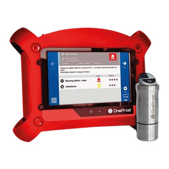
HAWK is available in 2 versions. The HAWK (red rubber) is for safe area, and the HAWK-EX (black rubber) for ATEX Zone II area. All functionalities described in this manual are applicable to both versions. -
Page 7: User Interface
1.4 U SER INTERFACE HAWK starts on its “Home screen”. It is a touch screen and a simple pressure on it gives access to the application modules installed on the instrument and to 2 side panels: Access to application modules... -
Page 8: Built-In Sensors
1.5.2 Connectors E to I behind the trapdoor Those connectors are behind a trapdoor. It must remain close in industrial environment to preserve the IP65 protection. Use those connectors only in office environment. Connector E: Power supply input Connector F: Ethernet RJ45 ... -
Page 9: Wireless Sensor
1.7 W IRELESS ENSOR HAWK can be used with a wireless triaxial accelerometer (WLS Sensor). This chapter described how to use HAWK with this sensor. 1.7.1 WLS sensor battery Use the USB cable and charger supplied with the sensor. The connector is protected by the rubber cap on the top of the sensor. -
Page 10: Data Exchange With Pc
Blank any status 1.8 D ATA EXCHANGE WITH HAWK can exchange data with the PC when the Communication module is run from the home screen. See below the different settings according to the type of communication. Once the communication is established, you can also use the NEST software to upload or download routes. - Page 11 Once the setting is done, to access the data use HAWK IP address, e.g., in the Explorer type “\\192.168.1.10\Data”. PC- HAWK connection through LAN Network: On PC: Setup Network DHCP = Yes On HAWK: Shortcuts > Setting >...
-
Page 12: Status Indications
Once the setting is done, to access the data use HAWK IP address, e.g., in the Explorer type “\\192.168.1.xxx\Data”. Note: this type of communication can also be used if the WLS Sensor is switched off. Wi-Fi LAN connection PC- HAWK setting without WLS sensor: Note: WLS sensor cannot be used simultaneously with this mode. -
Page 13: Shortcuts Panel
1.10 S HORTCUTS PANEL From any screen, button opens the Shortcuts panel. It gives direct access to a group of functions. The list of accessible functions depends of the current screen. 1.10.1 Photo From the Collect module, measurement list screen: take an inspection picture ... - Page 14 1.10.2 Text note From Collect module, measurement list screen: input text inspection note directly from the keyboard or from a list of predefined notes. The list of predefined notes is only available if this list is created in PC database (in XPR menu “Libraries/Predefined notes”) ...
- Page 15 Make sure you set the volume to a low level before starting to listen Play: listen to the comment For this function, you must have the optional 3.5 mm jack adapter on connector D (ref: CPC1229000 - HAWK ECTD-JACKF). 1.10.5 Barcode...
- Page 16 2 times. Use to return to the initial frequency. 1.10.9 Screenshot From anywhere, you can save a screen copy. Images are stored in folder “Screenshots”. Connect your PC to HAWK to copy them (see § 1.8). Brand of ACOEM...
-
Page 17: Battery Management
1.11.2 Battery replacement Safety instructions: Do not use batteries other than type PIL1133 provided for HAWK and identified as 01dB Metravib WILPA 2344A Do not open or disassemble the battery pack. The pack includes protections and an assembly essential for the safety that should be changed in no case. - Page 18 Do not short-circuit the terminals of the battery connector. For safety reasons, the battery pack includes an internal non-resettable fuse. A short-circuit makes it unusable. Respect voltage, current and temperature indicated on the label of the battery. Do not expose the battery to water or condensation. Do not place the battery in fire or near any other source of temperature (>...
-
Page 19: Remote Display & Control Function
Install Real VNC Viewer ® on the PC HAWK must be first networked by Ethernet (see § 1.8.3) or by Wi-Fi (see § 1.8.4) with the PC To work also with WLS Sensor, use the ‘Direct Wi-Fi connection PC- HAWK-WLS setting’ configuration. -
Page 20: Chapter 2. General Settings
CHAPTER 2. ENERAL SETTINGS Access: Shortcuts panel > Settings 2.1 C OLLECT Possibility to protect* the modification of some route data: sensor position pictogram, location or point picture, barcode, rotation speed for measurement done by tachometer Possibility to protect* the functions ‘Delete’ and ‘Reset’ for routes not downloaded. ... -
Page 21: Wireless Sensor
Check if HAWK is set to work with a WLS sensor: Shortcuts > Setting > > Accelerometer link = Wireless Check if the serial number of the sensor is that declared in HAWK Shortcuts > Setting > Wireless sensor ... -
Page 22: Tachometer
2.4 T ACHOMETER First tab: Tachometer setup Adjustment of tachometer parameters: Input range: select the range according to the tachometer signal : +/-10V, 0/-24V, 0/+24V Coupling: DC: default setting AC: a 0.3Hz high-pass filter is applied. This can be used if the DC component of the signal is changing during measurement (for example: signal from a proximity probe during run-up / coast-down). -
Page 23: Camera
2.6 C AMERA Set the access to the barcode reader and the camera. The access to the camera can be protected by password (The protection is applied if you define a password on the last line of Settings > About). 2.7 T OUCHSCREEN ... -
Page 24: Date - Language
– 2.9 D LANGUAGE Input of: Date: format must be DD/MM/YYYY Time: format must be HH:MM Time zone: select your time zone in the list Daylight saving: Yes or No Language: select in the list ... -
Page 25: Data Management
Put update firmware (.czip file) on a USB memory key. Note: the memory must have only one update file. Connect the system to its power supply. Plug the USB memory key in HAWK connector G. Shortcuts > Setting > Update firmware ... -
Page 26: Calibration
Possibility to disable Wi-Fi to extend the battery life. 2.16 M IX OF WIRED AND WIRELESS SENSORS It is possible to use HAWK with WLS sensor or with 1 to 4 wired inputs. The point to channel association depends on: ... - Page 27 Not compatible with triaxial measurement: all other cases or 4 points on the same location. Example: 4 points on 2 bearings Point Location Direction Pt1-H MOTOR None (-) Pt1-V MOTOR None (-) Pt2-H MOTOR None (-) Pt2-V MOTOR None (-) * Machine shaft direction, location and measurement direction are automatically created in NEST Machine setup.
-
Page 28: Chapter 3. Supervisor Module
The HAWK Supervisor solution requires the use of both HAWK portable device to make the measurement and diagnosis in the field, and a computer with access to the NEST software for measurement setup and reporting purposes. -
Page 29: First Connection To The Nest Software
3.3 F NEST IRST CONNECTION TO THE SOFTWARE Type www.oneprod-cloud.com in your web browser. A NEST shortcut will be placed automatically on your computer desktop. If required, the Microsoft Silverlight Plugin will be installed automatically as well. Proceed as follows:... - Page 30 Automatic diagnosis: the generation of measurement is fully automatic and an automatic diagnosis is performed after measurement in HAWK Supervisor. Machine type: select if machine is at fixed rotation speed (speed not measured and not modifiable) or if machine is at variable speed (speed is measured). In this 2 case, select also how the rotation speed is measured.
- Page 31 For Automatic diagnosis mode and fixed speed machine, the value must be as close as possible from the effective rotation speed (+/- 20 CPM). HAWK gives the possibility to adjust the rotation speed with its stroboscope. In this case, when downloading the route, the new rotation speed is used to update NEST initial setting.
- Page 32 Gearbox transmission: Bearing type: Rolling element or Journal. Note: For journal bearings, bearing defects specific to this type are not detected in this version. Mounting: Rigid or Flexible Multiplication factor: output speed / input speed ratio (this value is mandatory): ...
- Page 33 Add: add the component selected in the bar to the working area. Delete: delete the selected component from the working area. Set as photo: the drawing of the working area is used for the machine display in NEST machine supervision or HAWK (map mode). Working area...
- Page 34 Operating condition: definition of the operating conditions of the machine. Up to 9 conditions can be created. The list is loaded in HAWK data collector. The operator can then select the operating condition when he made his measurements Contextual functions: ...
-
Page 35: Load A Machine On Hawk
From HAWK home screen select the “Communication” module: On NEST software: Load directly one machine Connect HAWK connector H with a USB port of the PC From Machine supervision module or setup machine module , select a machine and click on the contextual function “Load”. -
Page 36: Make Measurements With Hawk Supervisor
3.6 M HAWK S AKE MEASUREMENTS WITH UPERVISOR 3.6.1 HAWK Supervisor module guideline Machine list Acquisition Automatic Diagnosis Measurement list Measurement display Machine exploration Brand of ACOEM... - Page 37 3.6.2 Machine list screen This screen lists all the machines loaded in the instrument. The first one “OFF_ROUTE” is specific and always there. It is used to take make measurement on machines not loaded from the PC. For more details, see § Erreur ! Source du renvoi introuvable.
- Page 38 Go down to the item selected in the list or in the map. Go to list mode Go to map mode. Search: input a character string and search in the list the next machine name including it. This function is in List mode only Return to route list Access to OFF_ROUTE additional functions.
- Page 39 Inspection picture: see § Erreur ! Source du renvoi introuvable.. Inspection note: see § Erreur ! Source du renvoi introuvable.. Inspection vocal note: see § Erreur ! Source du renvoi introuvable.. Point identification with QRcode: see § 1.10.5. Listen sensor signal: see § 1.10.6. Use the pyrometer for temperature measurement: see §...
- Page 40 To set it click on and select the sensor pictogram corresponding to the position of the sensor on the bearing. For WLS sensor, the X axis is marked by ACOEM or ONEPROD logo and a point at the base of the sensor.
- Page 41 Sensor position picture: It is possible to replace the pictogram by a picture of the sensor. This picture is useful if you intend to do several controls on the same machine over the time. It can help the user to position the sensor exactly at the same place at each control.
-
Page 42: Display Measurements
Battery level of the sensor Status message: If a defect is detected during the acquisition a pop-up message is displayed at the end of the acquisition. It indicates the status of each channel. 3.7 D ISPLAY MEASUREMENTS This function displays the result of the selected measurement. If acquisition is not yet performed, it displays directly the live values. - Page 43 At the top: amplitude at the fundamental frequency Side band (spectrum only) The central cursor and the first side band cursor are automatically adjusted on the true frequency of a maximun by interpolation. Side band frequencies in coincindence with a maximum are marked by a sign.
-
Page 44: Run Automatic Diagnosis
3.8 R UN AUTOMATIC DIAGNOSIS This function gives directly the machine diagnosis instantly after your measurement. The diagnosis information is: A pictogram giving the general status of the machine: The machine is good The machine is still acceptable The machine is not acceptable ... -
Page 45: Add Comments To The Diagnosis
Inspection note: see also § 1.10.2. The text inspection note is available in HAWK for the end user as long as the measurement is not deleted, but also automatically to a remote expert if a request for assistance is made (see § 3.12). -
Page 46: Print A Report From Nest Supervision Module
3.11.2 Advice display type The advice display type allows you to quickly access the machine health status according to the expert advice (HAWK or ONEPROD remote expert). 3.11.2.1 Global view In a global view, machines and sites are represented by labels, whereby a machine label exhibits the colour of the last advice issued and contains the following information: ... - Page 47 In the secondary information area: The last expert advice attributed to the machine (by HAWK or ONEPROD remote expert). The date of this advice A location label contains the following information: ...
-
Page 48: Ask For Remote Assistance From Nest Supervision Module
Initial recommendation Once validated, the request is sent to a ONEPROD Expert along with the information of the machine to be analysed along with your comments. The remote expert will notify you by e-mail, as soon as the results of his analysis are available on the cloud. -
Page 49: Copy / Paste Machines On Hawk
It is possible at any time to create a new machine by copying/pasting any machine from the list of machines previously loaded on HAWK by going to the “OFF_ROUTE” mode, available from the list of machines. You can load a several machines setups used as models for your OFF_ROUTE measurements Important Note: ... -
Page 50: Chapter 4. Balancing Module
HAWK is a universal tool that can be adapted to the entire base of machines to be balanced on site, regardless of the size and complexity of the rotors, by managing up to 4 balancing planes: ... -
Page 51: Balancing Module Guideline
4.1 B ALANCING MODULE GUIDELINE Folder list Balancing list Report Setup Free Run Steps browser Trial Run (X Plane number) Measurement Definition Balancing result Measurement Result Definition Trim steps (up to 8) Measurement Result Definition Brand of ACOEM... -
Page 52: Folder List
4.2 F OLDER LIST This creates a management folder used to sort balancing tests. A folder can be used to store, for example, tests on the same machine or all balancing done for a customer. Functions of the screen: Go to selected folder: see § 4.3. Create a new folder in the list. -
Page 53: Installing The Equipment
4.4 I NSTALLING THE EQUIPMENT To perform the balancing measurements, you should have a triggering device and at least one vibration sensor available. Take care to not change the position of the sensors during the entire balancing process. 4.4.1 Vibration sensor Note: as phase measurement is required, Balancing module cannot be used with the WLS Sensor. -
Page 54: Setup
ACC1056000 Three-finger clamp For the setting of the tachometer input see § 2.4. A pulse is sent to HAWK for each rotation of the machine. 4.5 S ETUP This screen includes 4 tabs. They are used to define the balancing and the type of measurement used to perform the balancing process. - Page 55 4.5.1 Machine setup This tab gives access to following parameters: Number of planes: 1 to 4 This refers to the number of planes on which balancing weights are to be installed. This number also determines the number of measurement points, as well as the number of runs required to perform the balancing: Number of points = number of planes Number of runs = 1 (Free run) + number of planes (Trial runs)
- Page 56 4.5.2 Measurement setup This tab gives access to following parameters: Number of channels: 1 or 2. This value is only accessible for a 2-plane balancing. If 1 is selected at each run, each point is measured one after the other one. In all other cases, the number of channels is equal to the number of planes.
-
Page 57: Run-Out Measurement
4.5.4 Units and control setup This tab gives access to following parameters: Trial weight unit: g, kg, lb, oz Radius unit: mm, cm, m, in Machine class (ISO 1940): select the machine type in the list (G0.4 to G4000). The balancing result is compared with the selected class. -
Page 58: Free Run
Quality of measurement: gives access to the dispersion of vibration and rotation speed. HAWK includes an automatic analysis of the measurement. If an abnormal event is detected the measurement screen display an alert pictogram ( ). -
Page 59: Trial Run
4.8 T RIAL RUN Known unbalance is added on the rotor to compute the relation between measured vibration and rotor unbalance. The number of trial runs is equal to the number of balancing planes. 4.8.1 Trial run definition You must indicate the value of the weight and its angular position in each of the balancing planes. Carefully observe the angle convention (direction of rotation = positive direction of angles). - Page 60 Symbols used on definition screen: , … Trial runs: Balancing run: , … Trim runs: Note: Negative weight is symbolized by a white square. Example: Weights of other runs are symbolized with fine borders and parentheses: ...
-
Page 61: Balancing Result
4.9 B ALANCING RESULT 4.9.1 Result After the last trial run, the instrument displays computed balancing weights. It is possible to select: The reference run: indicate the run to which balancing weights are to be added. Generally, it is either the free run (run without any trial weight), or the last run (run with all trial weights) when it is difficult or impossible to remove trial weight. -
Page 62: Trim Steps
4.10 T RIM STEPS The trim steps are used to iterate up to 8 additional measurements used to improve the result of the balancing. 4.10.1 Trim result This screen shows: The balancing quality grade estimation. Notes: To display the quality, it is necessary to have the rotor weight and radius not equal to 0. The quality is computed only for 1 or 2 plane balancing. -
Page 63: Report
4.13 R EPORT 4.13.1 Picture and comment Before generating the report, you can document the balancing with pictures and a comment. From any step of the balancing, from the shortcut panel , you can use following functions: Add a picture. You can take up to 6 pictures to document the report: global picture of the machine, sensor installation, weight installation…... -
Page 64: Chapter 5. Maintenance
CHAPTER 5. AINTENANCE 5.1 RESET Open the connector trapdoor. The reset button is in front of the small hole. Press it with a thin tip (a paperclip for example) during 5 or 6 seconds. The instrument restarts on the home screen. No data are deleted with this operation. - Page 65 5.7 S CREEN FRAME PROTECTION A screen protection frame is supplied with HAWK for safe area. It is recommended to install it before using the instrument in an environment that can damage the screen (mainly dust). Installation instructions: If necessary, clean the screen and the area on which the frame applies. Use only a soft cloth dampened...
-
Page 66: Chapter 6. Appendix
CHAPTER 6. PPENDIX 6.1 A 1: D PPENDIX ATA STORAGE ORGANIZATION When the instrument is connected to the PC (see § 1.8), you can see the contents of its memory. The organization is as follows: ‘Balancing’: Data base including all the balancing tests ... - Page 67 200 chemin des Ormeaux 69578 LIMONEST – FRANCE Tel.: +33 (0)4 72 52 48 00 www.acoemgroup.com Asia Tel. +66 (2) 7112 293 – Fax +66 (2) 7112 293 South America Tel. + 55 (11) 5089 6460 – Fax +55 (11) 5089 6454 Brand of ACOEM...
Need help?
Do you have a question about the HAWK and is the answer not in the manual?
Questions and answers