Advertisement
Table of Contents
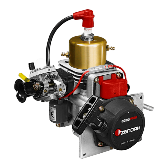
OWNER'S MANUAL
Model: G300PUM
for radio control Boat
WARNING
• This engine is designed for radio controlled boat use.
• When replacing parts, use only parts which have been
certified by Zenoah.
• Zenoah assumes that no responsibility for this engine
that is modified or used for any other applications.
• Purchaser has all responsibilities against any laws
and regulations existing in the country, Zenoah is
exempt from such laws and regulations.
• Read and completely understand this OWNER'S
MANUAL before operating this engine.
114 06 37-26 (1808)
Advertisement
Table of Contents

Related Manuals for Zenoah G300PUM


Summary of Contents for Zenoah G300PUM
- Page 1 • This engine is designed for radio controlled boat use. • When replacing parts, use only parts which have been certified by Zenoah. • Zenoah assumes that no responsibility for this engine that is modified or used for any other applications. • Purchaser has all responsibilities against any laws and regulations existing in the country, Zenoah is exempt from such laws and regulations.
-
Page 2: Table Of Contents
WARNING AVERTISSEMENT ADVERTENCIA Les échappements du moteur de Los gases de escape del motor de The engine exhaust from this ce produit contiennent des este producto contienen product contains chemicals produits chimiques connus par sustancias químicas conocidas known to the State of California to l’Etat de Californie comme étant por el Estado de California como cause cancer, birth defects or... -
Page 3: Safety Precautions
1. Safety Precautions • This manual describes the engine. For its mounting and control, see the instruction manual provided by model boat manufacturer. • This engine is designed for model boat use. If it is used for any other purpose, we cannot be responsible for its reliability, safety and any laws/regulations in the country. -
Page 4: Engine Assembling
2. Gasket (T2075-13150) 3. Carburetor (580349001) 4. Air-funnel (848ES08300) 5. Spacer (1142-83110) 6. Screw (0263-30555) G300PUM CAUTION Make sure that gasket and carburetor are mounted as described in fig.1. The engine does not start if carburetor is mounted upside down position. -
Page 5: Engine Mounting
3. Engine Mounting Make sure that the engine is to be mounted according to the instruction manual provided by model boat manufacturer. In case such instruction manual is not available, make sure that the engine should be mounted at least by 4 points both at engine's PTO side and recoil starter side. [ Note ] 1) Be sure to set flat washers or metal plates on the reverse side of the mount to prevent bolts from sinking into the mount. -
Page 6: Screw Propeller
4. Screw-Propeller The exhaust system (e.g., muffler) is not equipped with this engine as standard. When you select the exhaust system, check the engine speed (rpm) when the maximum output is generated by using the exhaust system you are going to select. And then decide the appropriate screw-propeller that would meet such engine speed (rpm) that the exhaust system requires. -
Page 7: Fuel
5. Fuel • Mixed gasoline (octane over 90) and high grade 2 cycle engine oil (mixing use type; JASO:FC grade or ISO: LEGC grade) at mixing ratio 25 : 1. • The mixing ratio is according to the oil recommendation. [ NOTE ] 1) Gasoline may contain maximum of 10% Ethanol (grain alcohol) or up to 15% MTBE (Methyl tertiary-butyl ether). -
Page 8: Starting
6. Starting ● How to start a. Put fuel into the fuel tank. b. While holding the equipment, pull out the starter rope swiftly. c. In cold-starting, when the engine doesn't start. Partially choke the air-intake of carburetor by finger to make engine fire. 7. -
Page 9: Carburetor Adjustment
8. Carburetor Adjustment The carburetor is provided with 3 adjust screws they may need a little adjustment depending on the temperature, atmospheric pressure (altitude), etc. of the area where the engine is used. Start the engine without making any adjustments. Make readjustments only when the engine shows any mal-running. - Page 10 8. Carburetor Adjustment Idle Screw: Turning this screw clockwise increases the idling R.P.M. Turning it counterclockwise decreases the idling R.P.M Low Speed needle: This is the fuel adjust screw (not the air screw). Turning this needle clockwise makes the mixture gas leaner and turning it counterclockwise makes it richer. Set this needle at a position which is 1/4 open from best mixture (maximum R.P.M.) position.
-
Page 11: Engine Break-In
9. Engine Break-In No specific break-in is required. The engine is gradually broken-in as it is used and the output is also gradually increased. For checking the whole conditions of the boat, it may be better to operate the engine at slow RPM for 1/3 tank and mid-high RPM for 2/3 tank. 10. -
Page 12: Maintenance
11. Maintenance 1) MAINTENANCE CHART Before Every Every Items Action 25 hours 100 hours Note Leakage, ✔ ✔ ✔ Check Damage/Crack ✔ ✔ ✔ Idling Speed Check/Adjust ✔ ✔ Spark Plug(gap) Check/Adjust Replace if necessary ✔ ✔ ↑ Cylinder(barrel) Check/Cleaning ✔... - Page 13 11. Maintenance 2) Specifications & Technical Data ITEMS SPECIFICATIONS Engine model G300PUM Type Water Cooled Bore x stroke (mm) 36 x 29 Displacement 29.5 Effective Compression Ratio Carburetor type Walbro WT-1048 Venturi (mm) ø13.5 Air funel — Starting Recoil Starter...
- Page 14 11. Maintenance 3) MAINTENANCE SPECIFICATIONS G300PUM Items Standard Limit Measuring Device Remarks Cylinder Bore (mm) ø36 Plating damaged Eye Checking At the skirt end and the right Diameter (mm) ø35.97 ø35.87 Micro Meter angle to the piston pin. Piston Ring 1.01...
- Page 15 11. Maintenance 4) CARBURETOR Items Unit Standard Measuring Device Metering Lever set 1.65 ± 0.16 Vanier 0.16~0.26 Inlet Valve Opening Pressure Leak Tester kg/cm 1.6~2.6 0.08~0.18 Inlet Valve Closing Pressure Leak Tester kg/cm 0.8~1.8 5) IGNITION SYSTEM Items Standard Limit Measuring Device Remarks Spark Plug Air Gap (mm)
- Page 16 11. Maintenance 6) TIGHTENING TORQUE Standard Limit Items Screw Size Remarks N·m kg·cm N·m kg·cm Carburetor M5 (P=0.8) 2.9~3.9 30~40 Insulator M5 (P=0.8) 3.9~4.9 40~50 Rotor M8 (P=1.0) 12.7 9.8~14.7 100~150 Cylinder M5 (P=0.8) 4.9~8.8 50~90 Crankcase M5 (P=0.8) 4.9~6.9 50~70 Spark Plug M10 (P=1.0)
-
Page 17: Special Tools
12. Special Tools Part Name Part No. External Appearance Usage Puller Assy 577409701 To remove rotor. To hold crankshaft when disassembling/assembling Piston Stopper 4810-96220 the rotor. For socket screw of Hex Wrench 3304-97611 4mm, 5mm and 6mm. Snap Ring Pliers 5500-96110 To remove snap ring. -
Page 18: Trouble Shooting
13. Trouble Shooting 1) ENGINE DOES NOT START Description Cause Countermeasure No spark in the spark plug Spark Plug 1. Wet spark, plug electrodes Make them dry 2. Carbon deposited on the electrodes Cleaning 3. Insulation failure by insulator damage Exchange 4. - Page 19 13. Trouble Shooting 2) LACK OF POWER OR UNSTABLE RUNNING Description Cause Countermeasure 1. Air penetration from fuel pipe joints, etc Secure connection 2. Air penetration from intake tube joint or Change gasket or tightening screws carburetor joint 3. Water in fuel Change with good fuel 4.
-
Page 20: Parts List
14. Parts List... - Page 21 14. Parts List Q'TY/ Q'TY/ KEY# PART NUMBER DESCRIPTION REMARKS KEY# PART NUMBER DESCRIPTION REMARKS UNIT UNIT 577916501 CYLINDER 848ESZ7510 RECOIL ASSY 577901901 JACKET 1850-75130 • SPRING, spiral 07851-00515 JOINT 848E4075C0 • REEL 07000-13042 O-RING 3x42 848E4075G0 • SPRING T2076-12320 O-RING 1.5x15.5 848E4075D0 •...
- Page 22 14. Parts List Q'TY/ KEY# PART NUMBER DESCRIPTION REMARKS UNIT 580349001 CARBURETOR ASSY 3306-81380 • SCREEN 2630-81120 • COVER 3310-81130 • SCREW 3304-81140 • GASKET 1172-81150 • DIAPHRAGM 3356-81310 • VALVE, INLET 2850-81290 • GASKET, METERI 848HE081K0 • DIAPHRAGM 1488-81370 • SPRING 3310-81280 •...
-
Page 23: Warranty
And sold to the user directly or through 5) Exempt from Warranty distributor/manufacturer, shall entitle to be Zenoah shall not warrant this engine even if covered by this warranty. the fault has been caused during the period of 2) Limits of Warranty terms of Warranty, in case that. - Page 24 Head Office : 1-9 Minamidai, Kawagoe-city, Saitama, 350-1165 Japan Phone: (+81)49-243-1115 Fax: (+81)49-243-7197...
Need help?
Do you have a question about the G300PUM and is the answer not in the manual?
Questions and answers