Table of Contents
Advertisement
Quick Links
Thank you for purchasing a ZENOAH engine.
● Please read this Service Manual thoroughly and use the engine correctly. (For safety
reasons, please contact your sales dealer prior to using the engine if there is something
about it that you do not understand.)
● This engine has been designed for radio control airplanes. Please use it in conjunction with
the manuals for the models or radio control equipment you will be using.
● Modifications or use of the engine for other than its intended purpose is prohibited.
● We ask that the product be used only after it has been understood that the purchaser (user)
shall bear all obligations and responsibilities stipulated by law, local ordinance and the like
and that ZENOAH shall bear no responsibility whatsoever.
OWNER'S MANUAL
848EW093A1 (704)
Model: G200PU
Model code: X374320000
Advertisement
Table of Contents

Related Manuals for Zenoah G200PU-EI


Summary of Contents for Zenoah G200PU-EI
- Page 1 ● We ask that the product be used only after it has been understood that the purchaser (user) shall bear all obligations and responsibilities stipulated by law, local ordinance and the like and that ZENOAH shall bear no responsibility whatsoever.
-
Page 2: Table Of Contents
CONTENTS Specifications ...............3 Safety Precautions ...............4 Engine Assembly ..............6 DC Ignition Unit Mounting ............7 Fuel and Piping ..............8 Throttle Linkage and Engine Mounting ........9 Items to Confirm Before Starting the Engine......10 Starting the Engine.............11 Adjustments After Engine Startup ........12 Brake in ................13 Stopping the Engine............13 Engine Running Time............13 Maintenance...............14... -
Page 3: Specifications
SPECIFICATIONS ITEMS SPECIFICATIONS Engine model G200PU Displacement 20.1cm Bore x stroke ø32mm x 25mm Weight 990g (not including DC Ignition Unit) Carburetor type WT-811 Ignition Battery ignition; digital control Sparkplug Champion Y82 Rotating direction Counterclockwise (from PTO side) Starting method External motor Sensor gap 0.8 ~ 1.2mm (1.0mm ±... -
Page 4: Safety Precautions
SAFETY PRECAUTIONS ● These safety precautions are to prevent you and those in the vicinity from incurring harm or damage. Make sure to observe these precautions and to constantly strive to ensure safety. ● Safe use of the engine is your personal obligation and responsibility. Constantly take care to act with good judgment as you enjoy your hobbies. - Page 5 SAFETY PRECAUTIONS • Special caution must be taken with all propellers used. Make sure to use them correctly, in keeping with the manufacturers’ operating manuals, etc. Failure to do so could result in injury. • Please wear clothing that facilitates your safety. Remove all scarves, overly long sleeves, neckties and the like.
-
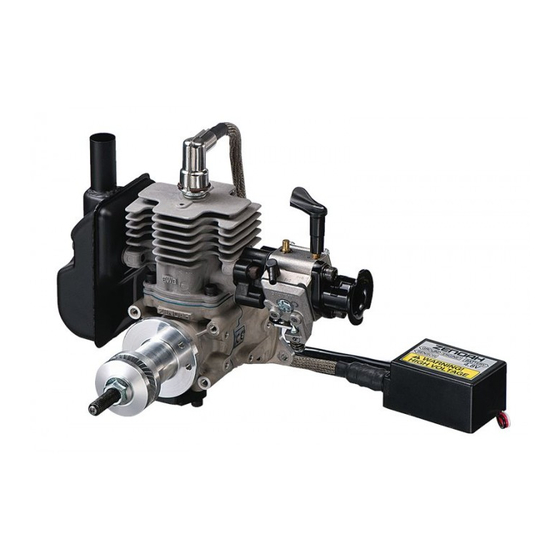
Page 6: Engine Assembly
ENGINE ASSEMBLY The carburetor, muffler, and air funnel have not been assembled. Please assemble them correctly, following the diagram shown below. Tightening Part Part no. Quantity Torque (N-m) 1. Bolt 01252-30540 2. Muffler 848EW015A0 3. Gasket 1140-13141 4. Gasket 848H7014C1 5. -
Page 7: Dc Ignition Unit Mounting
DC IGNITION UNIT MOUNTING 1. Make sure to install the power switch. 2. Push the sparkplug cap all the way over the sparkplug. (use gloves) 3. Fixate the unit within the fuselage, as shown in the diagram. Do not wrap surface D the unit by the sponge, cloth or the like. -
Page 8: Fuel And Piping
FUEL AND PIPING ● For gasoline, please use either regular or high octane, for cars. (The octane number should be 85 or higher.) ● For oil, use a high-performing mixed lubrication type of 2-cycle engine oil (F3C grade or ISO EGC grade) and make the fuel volume ratio 1 (oil) to 25-40 (gasoline). -
Page 9: Throttle Linkage And Engine Mounting
THROTTLE LINKAGE AND ENGINE MOUNTING ● Mount the throttle arm to Stopper screw the carburetor’s throttle shaft as shown in the Throttle arm Shaft diameter: 4mm diagram or use the throttle (not supplied) valve stopper plate located at opposite side. Claw nut x4 M4 bolt x4 ●... -
Page 10: Items To Confirm Before Starting The Engine
ITEMS TO CONFIRM BEFORE STARTING THE ENGINE ● Please determine the propeller to use in keeping with the airplane’s size, gross weight, and flight characteristics. If necessary, consult with someone who has the proper experience. Guidelines for an APC propeller: about 8.300rpm / 15x10, about 8,900rpm / 15x8 ●... -
Page 11: Starting The Engine
STARTING THE ENGINE ● Close the choke lever and open the throttle valve 10% to 15%. ● Pressing the tip of the starter to the engine’s spinner, press the start switch for 1-2 sec and let the engine rotate. ● If the engine has made an explosive sound, suspend the starting operation and start by opening the choke lever and rotating the engine using the starter. -
Page 12: Adjustments After Engine Startup
ADJUSTMENTS AFTER ENGINE STARTUP Standard settings: (A) ADJUSTING THE IDLING turns ● After engine startup, set the idling at about 2000rpm, turn the L needle to the right (to turns reduce fuel), and search for the position for the max. engine speed. From that position, turn the L needle about 1/4 (90°) to the left (to increase fuel), set the idling speed with the idle H needle L needle... -
Page 13: Brake In
BRAKE IN ● Different from a glow engine, this engine does not require any special brake in. ● After 5~10 tanks (2~3 hours), adjust the carburetor’s L and H needles if necessary. ● After about 5 hours’ running, the max. engine speed will be slightly increased from initial max.speed, owing to the engine having been conditioned. -
Page 14: Maintenance
MAINTENANCE To ensure safe use of the engine, make sure of the items specified in the table below. Before Every Every Item Inspection using 100h Cylinder, carburetor, muffler, ✔ ✔ ✔ Leakage & breakage crankcase, Fuel pipe, etc. ✔ ✔ ✔... -
Page 15: Tightening Torque Chart
TIGHTENING TORQUE CHART Tightening Torque Part Screw Size Kg-cm Remarks Cylinder M4 (P0.7) Sparkplug M10 (P1.0) Using the tool provided Muffler M5 (P0.8) Crankcase M4 (P0.7) Insulator M4 (P0.7) Carburetor M5 (P0.8) Sensor M4 (P0.7) Stud (hub) M6 (P1.0) Using a piston stopper & LOCK TIGHT Nut (propeller) M8 (P1.25) Using the tool provided... -
Page 16: Other Information
CAUTION: ● Remove the sensor. ● Make sure that nut turned with a spanner is nut on the propeller hub side. ● Use a commercial puller of the appropriate size. ● When reassembling the stud bolt, apply LOCK TIGHT to the M6 thread part. OTHER INFORMATION This information is to enable our customers to enjoy radio control airplanes more, but all customers must take responsibility if they implement it. -
Page 17: Parts List
PARTS LIST Q'TY/ KEY# PART NUMBER DESCRIPTION REMARKS UNIT 848EW08100 CARBURETOR ASSY • 3306-81380 SCREEN • 3080-81120 COVER • 3310-81130 SCREW • 3304-81140 GASKET • 1172-81150 DIAPHRAGM • 2850-81290 GASKET • 3310-81260 DIAPHRAGM • 3310-81280 METERING COVER • 2867-81270 SPRING •... - Page 18 PARTS LIST...
- Page 19 PARTS LIST Q'TY/ Q'TY/ KEY# PART NUMBER DESCRIPTION REMARKS KEY# PART NUMBER DESCRIPTION REMARKS UNIT UNIT 1 848EW012A1 CYLINDER 1152-43290 WASHER 2 848EW012B0 GASKET, cylinder 8488608000 NUT 8488441800 BOLT 27 848EW071N0 SENSOR 4 848EW014A0 INSULATOR 8488441400 BOLT 5 848EW014B1 GASKET, insulator 3699-92369 SPARK PLUG 848EW02110 CRANKCASE COMP.
-
Page 20: Warranty
WARRANTY ● Scope of Application This warranty applies only to the engines and parts manufactured by ZENOAH and sold directly or through distributors. ● Limit of Warranty This warranty shall apply only to trouble resulting from material defects and inferior assemblies that ZENOAH acknowledges.
Need help?
Do you have a question about the G200PU-EI and is the answer not in the manual?
Questions and answers