
Related Manuals for Noble DG-E


Summary of Contents for Noble DG-E
- Page 1 NOBLE GLASSWASHER DISHMACHINES INSTALLATION, OPERATION, AND SERVICE MANUAL DG-E Noble DG-E Manual • 07610-004-24-94-K...
- Page 2 REVISION HISTORY Revision Date Made by Process Details 7-15-15 Release to Production. Removed DG-D and all references to it. 12-18-15 Changed P/N 05330-100-01-10 to 05330-011-61-34, item #3 on pg.32. Changed drain connection information on pg. 2 (changed 2” to 4-22-16 2 1/2”...
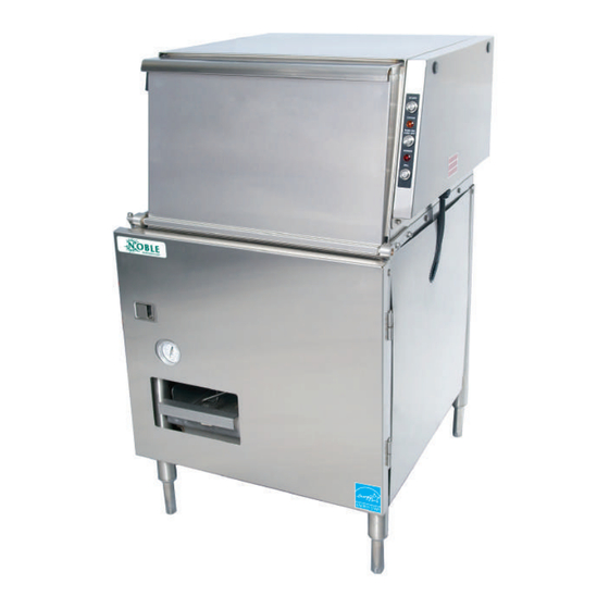
- Page 3 NOMENCLATURE DG-E Glasswasher dishmachine; low-temperature, chemical- sanitizing, with a sustaining heater and detergent, rinse-aid, and sanitizer chemical feeder pumps. The manufacturer provides technical support for all of the dishmachines detailed in this manual. We strongly recommend that you refer to...
-
Page 4: Table Of Contents
TABLE OF CONTENTS GUIDES Symbols ........................1 Abbreviations & Acronyms ..................1 SPECIFICATIONS Machine Dimensions ....................2 Operating Specifications ....................3 Electrical Requirements ....................4 INSTALLATION Installation Instructions ....................5 Inspection ......................5 Unpacking ......................5 Leveling ......................5 Facility Hot Water Heater .................5 Plumbing ......................5 Water Supply Connections ................6 Pressure Regulator ...................6 Shock Absorber ....................6 Drain Line ......................6... - Page 5 Tub ..........................31 Frame & Motor ......................34 Motor ..........................36 Sustaining Heater ......................37 Inlet Plumbing ......................38 Plumbing Options ......................39 Solenoid Valve Repair Kits ..................40 Door ..........................41 Front Panel ........................42 SCHEMATICS DG-E 115 V, 60 Hz, 1-Phase ..................43 DG-E Harness Connections ..................44...
-
Page 6: Symbols
GUIDES GUIDES SYMBOLS - Risk of Injury to Personnel WARNING - Risk of Damage to Equipment CAUTION - Risk of Electrical Shock - Caustic Chemicals - Reference Data Plate - Lockout Electrical Power - Important Note NOTICE - Instructions Hyperlink ABBREVIATIONS &... -
Page 7: Specifications
MACHINE DIMENSIONS SPECIFICATIONS LEGEND A - Water Inlet (1/2” NPT) B - Drain Connection (2” NPT) C - Electrical Connection 25 1/4 (641 mm) All dimensions from the floor can be increased 2 3/4” using the machine’s adjustable feet. 24 1/2 (622 mm) 36 3/4 (933 mm) -
Page 8: Operating Specifications
OPERATING SPECIFICATIONS SPECIFICATIONS OPERATING SPECS Operating Capacity: Racks per Hour (without load time) Dishes per Hour Glasses per Hour 1404 Gallons per Rack 1.15 Gallons per Hour 44.85 Operating Cycles (Seconds): Wash Time Rinse Time Dwell Time Total Cycle Time Wash Tank Capacity (Gallons): Water Temperatures (°F): Minimum Wash Temperature... -
Page 9: Electrical Requirements
WASH MOTOR 10.0 A AMPS *The DG-E is designed so the wash motor is never running when the sustaining SUST. heater is on. Total Load is based on the higher of the two loads. HEATER 16.0 A AMPS TOTAL 16.0 A*... -
Page 10: Installation
INSTRUCTIONS INSTALLATION INSPECTION Before installing the machine, check packaging and machine for damage. Damaged packaging might be an indication of damage to the machine. If there is any type of damage to both packaging and machine, do not throw away the packaging. The machine has been inspected at the factory before shipping and is expected to arrive Do not throw away in new, undamaged condition. -
Page 11: Water Supply Connections
INSTRUCTIONS INSTALLATION WATER SUPPLY If water hardness is higher than 3 GPG and a water softener is not being used, install the optional SPS into the water line between the facility water line and the CONNECTIONS: machine water line (installed at the factory). See the Plumbing Options page for more WATER HARDNESS information on the SPS. -
Page 12: Electrical Power Connections
INSTRUCTIONS INSTALLATION ELECTRICAL POWER Electrical and grounding conductors must comply with the applicable portions of the National Electric Code ANSI/NFPA 70 (latest edition) and/or other electrical codes. CONNECTIONS The data plate is located behind the door of the machine. Refer to the data plate for machine operating requirements, machine voltage, total amperage, and serial number. -
Page 13: Chemical Feeder Equipment
INSTRUCTIONS INSTALLATION CHEMICAL FEEDER This equipment is not recommended for use with deionized water or other aggressive fluids. Use of deionized water or other aggressive fluids will result in corrosion and failure of EQUIPMENT materials/components and will void the manufacturer's warranty. CAUTION! Chorine-based sanitizers can damage the machine if the chemical solution is too strong. -
Page 14: Cycle Timer Instructions
CYCLE TIMER INSTRUCTIONS INSTALLATION OVERVIEW Adjustable SELECT CYCLE STEP TO ADJUST PRESS SAVE TO EXIT Cycle Steps LEDs NOTICE • Drain Machines with serial numbers • Fill RINSE CYCLE PUMP DRAIN FILL SANI DETER SPARE • Sanitizer before 21H396817 have the old •... - Page 15 CYCLE TIMER INSTRUCTIONS INSTALLATION CHANGING CYCLE 1. Press button for step being changed. The LED for that step will come on. STEP TIMES SELECT CYCLE STEP TO ADJUST PRESS SAVE TO EXIT The first two steps RINSE CYCLE PUMP DRAIN FILL SANI DETER...
- Page 16 CYCLE TIMER INSTRUCTIONS INSTALLATION RESETTING TO 1. Press and hold CYCLE COUNT button and DOWN ARROW button (under STEP DURATION) simultaneously for 3–4 seconds. FACTORY DEFAULTS SELECT CYCLE STEP TO ADJUST PRESS SAVE TO EXIT RINSE CYCLE PUMP DRAIN FILL SANI DETER SPARE...
- Page 17 CYCLE TIMER INSTRUCTIONS INSTALLATION PLANT TEST MODE 1. Press and hold CYCLE COUNT button and DOWN ARROW button (under STEP START TIME) simultaneously for 3–4 seconds. SELECT CYCLE STEP TO ADJUST PRESS SAVE TO EXIT RINSE CYCLE PUMP DRAIN FILL SANI DETER SPARE...
-
Page 18: Operation Instructions
INSTRUCTIONS OPERATION PREPARATION Before operating the machine, verify the following: • Strainers are clean and in place. • Drain stopper is installed. • Wash/rinse arm is screwed securely into place and end-caps are tight. • Wash/rinse arm rotates freely. POWER UP To energize the machine, turn on power at the service breaker. - Page 19 INSTRUCTIONS OPERATION INITIAL After filling the heater tank, the heater element must be enabled. The machine is shipped from the factory with the heater element disabled. This is done to ensure START-UP that the heater element is not damaged by energizing the element without the element being submerged in water.
-
Page 20: Ware Preparation
INSTRUCTIONS OPERATION WARE Proper preparation of ware is essential for the smooth and efficient operation of the machine, resulting in fewer rewashes and less detergent used. Any ware loaded PREPARATION inside the machine should have all solid food waste and scraps removed. Ware should be sprayed-down before being placed in the machine. -
Page 21: Operational Inspection
INSTRUCTIONS OPERATION OPERATIONAL As the workday progresses, operators should regularly inspect the strainers to ensure they have not become clogged. If the strainers become clogged, it will INSPECTION reduce the washing capability of the machine. SHUTDOWN & 1. Turn machine off by pushing ON/OFF button. 2. -
Page 22: Detergent Control
INSTRUCTIONS OPERATION DETERGENT Detergent usage and water hardness are two factors that greatly contribute to the machine's operating efficiency. Using the proper amount of detergent can become a CONTROL source of substantial savings. A qualified water-treatment specialist can determine what is needed for maximum efficiency from the detergent. •... -
Page 23: Deliming
INSTRUCTIONS OPERATION DELIMING To maintain the machine at its optimum performance level, lime and corrosion deposits must be removed. The frequency for deliming will be based on water conditions. A deliming solution is available from your chemical supplier. Read and follow all instructions on the label. To delime the machine: If this machine is equipped with the SPS... -
Page 24: Preventative Maintenance
PREVENTATIVE MAINTENANCE MAINTENANCE PREVENTATIVE The manufacturer highly recommends that any maintenance and repairs not specifically discussed in this manual only be performed by qualified service personnel. MAINTENANCE Performing maintenance on the machine may void a warranty. By following the operating and cleaning instructions in this manual, users should get the most efficient results from the machine. -
Page 25: Troubleshooting
TROUBLESHOOTING TROUBLESHOOTING PROBLEM POSSIBLE CAUSE REMEDY Water overflow 1. Clogged drain. 1. Remove obstruction. from bottom of door. 2. Machine not level. 2. Level machine or increase height to the front. 3. Excessive inlet pressure. 3. Install pressure reducing valve or adjust if one is present. Ensure flow meets data plate specification. - Page 26 TROUBLESHOOTING TROUBLESHOOTING PROBLEM POSSIBLE CAUSE REMEDY Wash 1. Check that white/blue wires are 1. See Initial Start-up section. temperature connected. not at required reading. 2. Defective thermometer. 2. Replace. 3. Defective thermostat. 3. Adjust or replace thermostat. 4. Sustaining heater defective. 4.
-
Page 27: Control Box
CONTROL BOX PARTS 9 10 Normal/Delime Rinse-aid/Detergent Sanitizer NOTICE *Machines with serial numbers before 21H396817 have the old previous manual. CAM timer. See 11 26 11 26 07610-004-24-94-K... - Page 28 CONTROL BOX PARTS 15 26 16 27 17 26 16 27 NOTICE *Machines with serial numbers before 21H396817 have the old 23 26 CAM timer. See previous manual. 24 25 26 21 22 07610-004-24-94-K...
- Page 29 CONTROL BOX PARTS ITEM DESCRIPTION PART NUMBER Complete Control Box Assembly 05700-003-36-55 Control Box Weldment 05700-003-09-42 Control Box Cover 05700-003-30-54 Decal, Warning - Disconnect Power 09905-004-08-16 Screw, 10-32 x 1/2’’ Long, Phillips Tusshead 05305-011-39-36 Decal, Peri-pump Prime 09905-003-32-56 Switch, Delime/Normal 05930-301-21-18 Detergent/Rinse-aid Pump Prime Switch 05930-011-35-27...
-
Page 30: Chemical Feeder Pump Components
CHEMICAL FEEDER PUMP COMPONENTS PARTS ITEM DESCRIPTION PART NUMBER Pump Housing 04320-111-37-09 Screw, 8-32 x 3/8" Phillips 05305-011-37-07 Roller, Plastic 04320-002-82-28 Pump Cover 04320-111-37-08 Screw, 6-32 x 3/4" Phillips 05305-011-37-05 Screw, 8-32 x 1/2" Phillips 05305-011-37-06 Tube, Squeeze, 8" 05700-003-22-89 Motor, 14 RPM 04320-111-35-13 Motor, 36 RPM... -
Page 31: Peri-Pump Box
PERI-PUMP BOX PARTS ITEM DESCRIPTION PART NUMBER Peri-pump Assembly, 36 RPM 05700-004-71-60 Peri-pump Assembly, 14 RPM 05700-004-71-61 Drip Channel 05700-003-32-89 Peri-pump Box 05700-003-32-00 Peri-pump Box Cover 05700-003-33-80 Fitting, Conduit, Heyco 1/2’’ (behind box) 05975-011-65-51 Clamp, 5/8” Nylon (inside box) 04730-011-39-01 Clamp, 1”... -
Page 32: Electrical Connection Box
ELECTRICAL CONNECTION BOX PARTS ITEM DESCRIPTION PART NUMBER Box, Power Junction Weldment 05700-003-30-58 Terminal Block Spacer 05700-011-40-05 Terminal Block 05940-500-09-61 Locknut, 6-32 with Nylon Insert 05310-373-03-00 Locknut, 10-24 with Nylon Insert 05310-373-01-00 Lug, Ground 05940-200-76-00 Decal, Power Connection 09905-011-47-64 Decal, Warning to Disconnect Power 09905-004-08-16 Screw, 10-32 x 1/2’’... -
Page 33: Frame
FRAME PARTS ITEM DESCRIPTION PART NUMBER Adjustable Foot 05340-002-14-55 Plate, Hinge Weldment 05700-003-10-11 Washer, Hinge Weldment 05700-002-54-62 Spacer, PB Bolt 05700-000-29-40 Clamp, Pipe 05700-000-35-05 Washer, 1/4-20 SS 05311-174-01-00 Keeper, Door Panel Latch 05700-003-09-31 Locknut, 1/4-20 SS Hex with Nylon Insert 05310-374-01-00 Nut, Hex 1/4-20 05310-274-01-00... -
Page 34: Hood
HOOD PARTS ITEM DESCRIPTION PART NUMBER Switch, 115 V Reed 05930-002-36-80 Bracket, Limit Switch 05700-021-71-18 Locknut, 10-24 with Nylon Insert 05310-373-01-00 Clamp, Pipe 5/8” 05700-000-35-06 Rack Rail Weldment 05700-002-45-67 Washer, 1/4”-20 I.D. 05311-174-01-00 Gasket, Switch Panel 05330-100-10-00 07610-004-24-94-K... -
Page 35: Switch Panel
SWITCH PANEL PARTS ITEM DESCRIPTION PART NUMBER Complete Switch Panel Assembly 05700-003-24-38 Switch Panel Weldment 05700-003-24-36 Switch, Prime Assembly 05700-003-14-91 Switch, On/Off Assembly 05700-003-14-92 Light, Amber 05945-504-06-18 Light, Red 05945-504-07-18 Decal, Switch Panel 09905-003-08-63 Fitting, .25-.546 05975-011-65-51 Plug, 3/4” Hole 04730-011-60-21 Locknut, 10-24 with Nylon Insert 05310-373-01-00... -
Page 36: Tub
PARTS 07610-004-24-94-K... - Page 37 PARTS ITEM DESCRIPTION PART NUMBER Lower Manifold Weldment 05700-002-45-51 Manifold Gasket 05700-111-35-03 Drain Seat Insert 05700-004-37-18 Spillway Gasket 05700-111-34-52 Spillway Weldment 05700-003-52-13 Locknut, 1/4-20 SS Hex with Nylon Insert 05310-374-01-00 Manifold O-Ring 05330-111-35-15 Modified Casting Wedge 09515-011-46-61 Bolt, 3/8-16 x 1 1/4” SS 05305-276-10-00 Washer, 3/8”...
- Page 38 PARTS ITEM DESCRIPTION PART NUMBER Clamp, 1” Nylon (not shown, located on tub bottom) 04730-002-41-88 Drain Solenoid Box Assembly 05700-003-09-61 Solenoid Box Weldment 05700-003-35-88 Drain Solenoid, 115 V 04810-200-11-00 Locknut, 10-24 with Nylon Insert 05310-373-01-00 Solenoid Box Cover 05700-003-30-25 Decal, Warning to Disconnect Power 09905-004-08-16 Fuse Holder Assembly, In-line 05920-004-55-23...
-
Page 39: Frame & Motor
FRAME & MOTOR PARTS See Motor Page See Inlet Plumbing Page See Sustaining Heater Page 07610-004-24-94-K... - Page 40 FRAME & MOTOR PARTS ITEM DESCRIPTION PART NUMBER Discharge Tube Connector 05700-011-70-34 Pump Suction Hose 05700-002-40-82 Discharge Hose Assembly 05700-002-45-58 Wash Restrictor 05700-002-84-69 Accumulator Strainer Weldment 05700-003-33-25 Accumulator Weldment 05700-002-51-95 Bolt, 1/4-20 x 1/2” 05305-274-02-00 Locknut, 1/4-20 SS Hex with Nylon Insert 05310-374-01-00 Washer, 1/4-20 SS 05311-174-01-00...
-
Page 41: Motor
MOTOR PARTS ITEM DESCRIPTION PART NUMBER Complete Pump & Motor Assembly 06105-004-28-95 Motor Only 06105-004-32-03 Case O-Ring 05330-002-81-83 05700-002-81-87 Seal Plate Mechanical Seal 05330-002-34-22 Case Capscrew 05305-002-81-88 Pump Casing 05700-002-85-01 Shim Kit 05700-002-82-58 Impeller Assembly 05700-002-81-86 Drain Plug (not shown) 04730-002-81-89 07610-004-24-94-K... -
Page 42: Sustaining Heater
SUSTAINING HEATER PARTS ITEM DESCRIPTION PART NUMBER Heater Tank 05700-003-25-40 Heater Gasket 05330-011-61-34 Sustaining Heater 04540-002-45-13 Lockwasher, Split 5/16” 05311-275-01-00 Nut, Hex 5/16-18 05310-275-01-00 Nut, Lock 6-32 Hex with Nylon Insert 05310-373-03-00 Spacer, 1/4” OD x 9/32” 09330-004-34-91 Thermostat, Elan Electric (Dual) 06685-004-17-27 Cover, Heater Box 05700-004-34-90... -
Page 43: Inlet Plumbing
INLET PLUMBING PARTS ITEM DESCRIPTION PART NUMBER Y-Strainer 04730-217-01-10 Nipple, Close, 1/2’’ NPT, Brass 04730-207-15-00 Valve, Solenoid, 1/2’’ NPT, 115 V 04810-100-12-18 Adaptor, 1/2’’ Fitting (CU to Male) 04730-401-03-01 Tube, Copper, 1/2’’ x 1 1/4” 05700-001-08-28 Union, 1/2’’ 04730-412-05-01 Elbow, 1/2” 04730-406-01-01 Tube, Copper, 1/2’’... -
Page 44: Plumbing Options
PLUMBING OPTIONS PARTS SHOCK ABSORBER (WATER ARRESTOR) OPTION Water Arrestor, 1/2” 06685-100-05-00 Tee, 1/2” x 1/2” x 1/2” 04730-211-27-00 Nipple, 1/2” NPT, Brass 04730-207-15-00 Water Arrestor Repair Kit (Plunger & O-ring) 06401-003-06-23 PRESSURE REGULATOR OPTION Water Pressure Regulator, 1/2” 05700-100-04-07 SCALE PREVENTION SYSTEM (SPS) OPTION Replacement Cartridge (inspect at least every 6 months) -
Page 45: Solenoid Valve Repair Kits
SOLENOID VALVE REPAIR KITS PARTS Screw Data Plate Coil and Housing Data Plate Valve Bonnet Spring & Plunger Kit Spring position is moved 06401-003-07-40 for clarity. Goes below the plunger. Cap Retainer O-Ring & Diaphragm Diaphragm 06401-003-07-41 Retainer Screen Retainer Components of Repair Kit 06401-003-06-23 Mesh Screen... -
Page 46: Door
DOOR PARTS Complete Door Assembly 05700-005-05-95 NOTICE Machines with serial numbers before 22H409822 have the old door. See earlier manual. ITEM DESCRIPTION PART NUMBER Magnet 05930-002-88-42 Magnet Cover 05700-004-07-38 Locknut, 6-32 SS Hex with Nylon Insert 05310-373-03-00 Bolt, 1/4-20 Eye 05306-002-55-59 Nut, Hex 1/4-20 05310-274-01-00... -
Page 47: Front Panel
FRONT PANEL PARTS ITEM DESCRIPTION PART NUMBER Complete Panel Assembly 05700-003-09-53 Panel Weldment 05700-003-09-54 Handle 05340-001-96-30 07610-004-24-94-K... -
Page 48: Schematics
DG-E 115 V, 60 HZ, 1-PHASE SCHEMATICS DG-E 07610-004-24-94-K... -
Page 49: Dg-E Harness Connections
DG-E HARNESS CONNECTIONS SCHEMATICS Probe SUSTAINING HEATER 07610-004-24-94-K... - Page 50 NOBLE GLASSWASHER DISHMACHINES Noble Warewashing • Lancaster, Pennsylvania www.nobleproducts.biz For Service Call 1-888-800-5672 Noble DG-E Manual • 07610-004-24-94-K...
Need help?
Do you have a question about the DG-E and is the answer not in the manual?
Questions and answers