Table of Contents
Advertisement
Quick Links
D o o r Ac t iv ati o n D e v i c e s
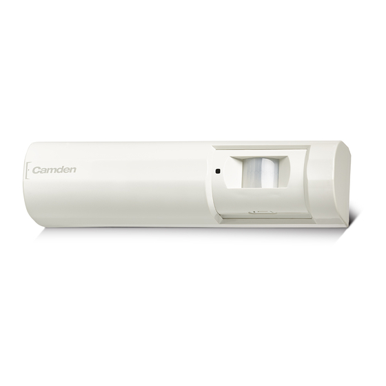
CM-RQE70A
PIR 'REQUEST TO EXIT' DETECTOR
Installation INSTRUCTIONS
THIS PACKAGE INCLUDES
(2) #6 x 3/4" Screws
(2) 3/16" Wall Plugs
(2) MOV's
1. GENERAL DESCRIPTION
Camden CM-RQE70A Request-to-Exit Sensor is a passive infrared (PIR)
detector designed for interior use. This device is UL listed as an access
control device under UL 294 Standard and is listed for Class I for UL
Canada under ULC-S319 when it is connected to a UL approved access
control system.
2. FEATURES
• Compact size, designed to mount on door frames
• On-board programming buttons. No dip switches
• (4) factory default operating modes, with the ability to customize mode
attributes
• Makes installation easy and fast
• Selectable Fail Safe/Fail Secure
• (2) Form 'C' contacts
• Momentary and latching relay modes
• Secondary activation device input
• Card/keypad input
• Door position switch input
• Request to exit input
• Built-in sounder (adjustable)
• Tamper switch
3. OPERATION
J4
SOUNDER
PARAMETER
J2
FIGURE 1 - COMPONENT LOCATIONS
TAMPER
LED
LENS
MODE
SWITCH
ADJUST
BP7175
FIGURE 1 - MOUNTING LOCATIONS
Self-Test
When power is first applied to the CM-RQE70A, the sensor will beep
once, then the unit performs a self-test to ensure its major functions are
within acceptable operating parameters. The self-test checks the input
voltage, switch operation and sensor function. If the sensor passes all
tests, there is a single beep and normal operation begins. If the sensor
fails any of the tests, the unit will provide a series of audible beeps
indicating the failure. This is take approximately 30 seconds.
Post-Test Failure Beeps
If the sensor fails a test, the unit will perform one or more short beeps,
followed by a long beep. This series of beeps is repeated continuously.
# of Short
Description
Beeps
1
The IR sensor did not settle to an acceptable level
during the test.
2
One of the 3 buttons, Mode, Parameter or Select is
detected as being pressed.
3
The Source Voltage to the CM-RQE70A is outside
of the range of 12 – 24V
4
The IR sensor is not changing over a large enough
range of values to reach its settle point
Fail Safe vs Fail Secure: Field Selectable
LOCK
DOWN
SCREW
These terms are used to describe the normal operating state of the
output relays. In Fail Safe Mode, the relays will be normally energized.
The relays will de-energize when a person is in the field of view (normal
operation) or when the power is removed due to an outage or other
external reasons. In Fail Secure Mode, the relays remain de-energized
normally. The relays will energize when a person is in the field of view
(normal operation). The relays remain de-energized during a power
outage, therefore, keeping the controlled device secure.
Page 1 of 6
Advertisement
Table of Contents

Related Manuals for CAMDEN CM-RQE70A

Summary of Contents for CAMDEN CM-RQE70A
- Page 1 Self-Test • Compact size, designed to mount on door frames When power is first applied to the CM-RQE70A, the sensor will beep • On-board programming buttons. No dip switches once, then the unit performs a self-test to ensure its major functions are •...
- Page 2 CM-RQE70A PIR ‘REQUEST TO EXIT’ DETECTOR INSTA L L AT I O N I NST RU CTI ONS External Disable/Enable Tamper Switch Input: Dry Dry contact outputs N/C are provided for interface to an alarm or access control systems. The Tamper Switch is connected to a spring that In this mode, the REX is enabled or disabled by an external device, such as compresses and closes the switch when the housing cover is installed.
- Page 3 30s (If the door is opened and closed, the timer is reduced to 2s) The Camden CM-RQE70A uses a plug-in wiring harness for all electrical Operating Function: Latched, Door Prop Open Alarm or Unauthorized connections. The Pin out is described below.
- Page 4 Flashing Factory Reset Regulatory Information The Camden CM-RQE70A Request to Exit sensor can be reset to factory The unit shall be installed in accordance with National Electrical Code defaults by pressing and holding the MODE and Adjust buttons. The ANSI/NFPA 70 and part 1 of the Canadian Electrical Code CSA C22.1, Sensor will start to beep.
- Page 5 CM-RQE70A PIR ‘REQUEST TO EXIT’ DETECTOR INSTAL LATION INS T RUCT IONS Maglock Maglock Notes: Notes: 1. Relay is set to Safe Mode in 1. Relay is set to Safe Mode in this application this application 2. Relay O/P2 is EMF protected.
- Page 6 CM-RQE70A PIR ‘REQUEST TO EXIT’ DETECTOR INSTAL L AT ION INS T RUCT IONS 6. COVERAGE INFORMATION in a larger detection area typically. The illustrations show the REX The detection area changes depending on the mounting height and sensor mounted at 7.5 (2.3m) Feet on a wall with the lens pointing angle of the lens of the REX sensor.
Need help?
Do you have a question about the CM-RQE70A and is the answer not in the manual?
Questions and answers