Dacor DYWS4 Installation Instructions Manual
Wine dispensing system
Hide thumbs
Also See for DYWS4:
- Manual (32 pages) ,
- Installation instructions manual (12 pages) ,
- Quick start (4 pages)
Table of Contents
Advertisement
Quick Links
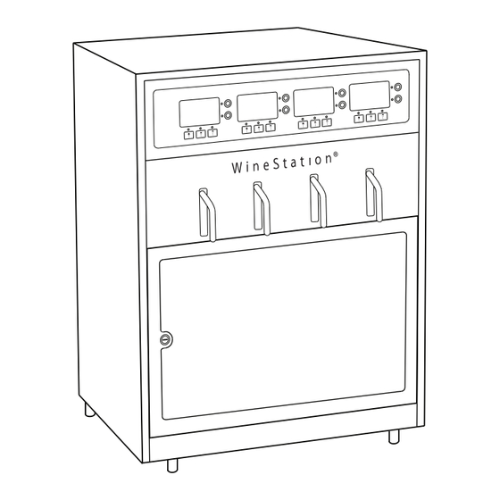
WINE DISPENSING SYSTEM MODEL: DYWS4
IMPORTANT: The wine dispensing utilizes a thermo-electric cooling system that can normally
cool the bottle bay to a temperature 25°F less than the ambient air outside the unit. This trim kit
limits system air circulation slightly, limiting the cooling capability to 22°F less than ambient. Be
sure that this limitation is acceptable before installing this kit.
Parts Included with kit
(8) #8 x 3/8 Phillips
head screws (PN 83263)
Top trim bracket
Left trim
piece
trim piece*
*The top and bottom trim pieces are identical, but
installed in the opposite orientation from each other.
Part Number AWSTK24
(9) #10 x 1/2 Phillips
head screws (PN 83022)
Top trim
piece*
Bottom
Trim Kit
(8) Flat head Phillips head
screws (PN 107578)
(1) Base divider
Bottom left trim
Right trim
piece
INSTALLATION
INSTRUCTIONS
(8) Fiber washers
(PN 83555)
(2) Base supports
Bottom right trim
bracket
bracket
Foam Strips
(1 long, 2 short)
Part No. 107554 Rev. A
Advertisement
Table of Contents

Subscribe to Our Youtube Channel
Related Manuals for Dacor DYWS4


Summary of Contents for Dacor DYWS4
- Page 1 WINE DISPENSING SYSTEM MODEL: DYWS4 INSTALLATION Trim Kit Part Number AWSTK24 INSTRUCTIONS IMPORTANT: The wine dispensing utilizes a thermo-electric cooling system that can normally cool the bottle bay to a temperature 25°F less than the ambient air outside the unit. This trim kit limits system air circulation slightly, limiting the cooling capability to 22°F less than ambient.
- Page 2 Wine Dispensing System Trim Kit Instructions Tools Required Phillips head Drill with 3/32” drill bit Tape measure Pencil screwdriver (for drilling pilot holes) Introduction For proper fit, the cutout dimensions shown are required. The spacing above and below the cutout are critical for ventilation purposes.
- Page 3 Wine Dispensing System Trim Kit Instructions Installation Instructions STEP 1 Peel the protective backing off of the longest of the 3 foam strips and at- tached it to the base divider as shown. STEP 2 Attach the (2) base pieces to the base divider using (4) #8 x 3/8 screws. The foam strip attached in step 1 goes toward the base pieces as shown below.
- Page 4 Wine Dispensing System Trim Kit Instructions STEP 3 Insert the base assembly, assembled in step 1, into the cutout with the divider toward the back. Center it left to right in the cutout using a ruler or tape measure. STEP 4 Using a pencil, mark 4 pilot hole locations in the front of the cabinet.
- Page 5 Wine Dispensing System Trim Kit Instructions STEP 7 Attach the bottom left and bottom right trim brackets to the front of the base assembly as shown, using (4) #8 x 3/8 screws. Base assembly Bottom left trim bracket Bottom right trim bracket Bottom Trim Bracket Installation STEP 8...
- Page 6 Wine Dispensing System Trim Kit Instructions STEP 9 Hold the top trim bracket in the mounting position on the top edge of the cut- out. Center it using a ruler or tape measure STEP 10 While holding the trim bracket in place, using a pencil, mark 3 pilot hole loca- tions in the underside of the top of the cabinet cutout.
- Page 7 Wine Dispensing System Trim Kit Instructions WARNING: Excessive weight hazard - Use two or more people to move and install the wine dispensing system. Failure to do so can result in back or other injury. STEP 13 With the help of at least one other person, place the wine dispensing system close the the cabinet cutout.
- Page 8 Fiber washers, use as necessary Flathead screw, 8 places Insert tabs into slots Trim Assembly and Installation Dacor ● 14425 Clark Avenue, City of Industry, CA 91745 ● Phone: (800) 793-0093 ● Fax: (626) 403-3130 ● www.dacor.com...
Need help?
Do you have a question about the DYWS4 and is the answer not in the manual?
Questions and answers