Advertisement
Available languages
Available languages
Quick Links
BSD-200
MICROWAVE BLINDSPOT DETECtION SYSTEM
CONGRATULATIONS on your choice of a CrimeStopper premium Universal, MICROWAVE BLINDSPOT DETECTION system.
This booklet contains all of the necessary information for connecting and using your MICROWAVE BLINDSPOT
DETECTION system. If any questions should arise, contact your installation facility or check out the Knowledge
Base at www.crimestopper.com
Installation manual
1230-62147-01-A
Advertisement

Related Manuals for CrimeStopper BSD-200


Summary of Contents for CrimeStopper BSD-200
- Page 1 BSD-200 MICROWAVE BLINDSPOT DETECtION SYSTEM CONGRATULATIONS on your choice of a CrimeStopper premium Universal, MICROWAVE BLINDSPOT DETECTION system. This booklet contains all of the necessary information for connecting and using your MICROWAVE BLINDSPOT DETECTION system. If any questions should arise, contact your installation facility or check out the Knowledge Base at www.crimestopper.com...
-
Page 2: Warranty
WHAT IS COVERED This warranty applies only to CrimeStopper products sold to consumers by authorized CrimeStopper dealers in the United States of America Products purchased by consumers from an Authorized CrimeStopper Dealer in any other country are covered only by that country’s Distributor and not by Rockford Corporation. -
Page 3: Table Of Contents
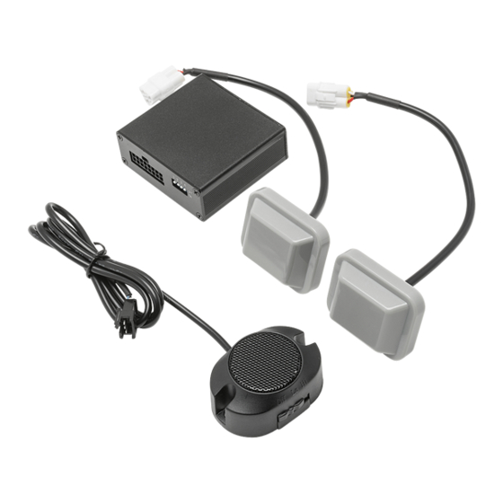
Introduction The BSD-200 is p remium Universal, microwave blindspot detection system. It works on both sides of the vehicle using state of the art microwave sensors designed specifically to go behind plastic bumpers providing detection of vehicles in the other lanes of traffic. This system was designed to be flexible enough that no matter the vehicle it is being installed into, you will have the correct parts needed. - Page 4 Wiring Harness AUDIBLE ALERT O Lo Hi OPTIONAL FLUSH OPTIONAL FLUSH MOUNT LED MOUNT LED LEFT SENSOR RIGHT SENSOR LEFT TURN SIGNAL INPUT - WHITE WIRE RIGHT TURN SIGNAL INPUT - GREY WIRE REVERSE SIGNAL INPUT - PURPLE WIRE GROUND INPUT - BLACK WIRE MAIN CONTROL UNIT...
- Page 5 wire harness layout RIGHT VISUAL ALERT RIGHT SENSOR Lo Hi LEFT SENSOR AUDIBLE ALERT LEFT VISUAL ALERT MAIN WIRING HARNESS...
-
Page 6: Wiring
mounting mcu/wiring Mounting the MCU (Main Control Unit) The system is designed to have the MCU mounted in the rear of the vehicle. Most vehicles have access to the turn signals and reverse trigger in the rear. 1. The MCU should be mounted on the driver’s side of the vehicle. Before mounting the MCU be sure to clean the area with an alcohol prep pad helping the adhesive stick better. - Page 7 wire connections Wiring Connections Before making any connections, it is recommend to use a DMM (Digital Multi Meter) to test the wiring. There are (5) wiring connections that are needed to be made. 1. Ground (Black) – Grounding the MCU should always be the first connection made to ensure that the system will not accidentally short out.
-
Page 8: Specifications
Specifications OPERATING VOLTAGE 9-16 V DC OPERATING CURRENT DRAW <200mA SENSITIVITY LEVEL LEVEL’S 1-4 LEVEL 1 - 26’ (8M) LEVEL 2 - 33’ (10M) LEVEL 3 - 39’ (12M) LEVLE 4 - 49’ (15M) NUMBER OF SENSORS 2 SENSOR ANGLE ADAPTORS YES, 3 PER SIDE ANGLE FINDERS YES, 3 AT DIFFERENT ANGLES SENSORS MOUNTING BEHIND BUMPER, NO DRILLING AUDIBLE ALERT YES, INCLUDED. -
Page 9: Key Features
Hidden Sensors – Microwave sensors are specifically designed to be mounted behind plastic bumpers allowing for a cleaner installation. Two Visual Alert Options – The BSD-200 comes with (2) LED options; there is both a surface and flush mount design (holesaw included). - Page 10 finding bumper angle Select the bumper shape that closely resembles the vehicle. BUMPER Car body Car body Car body SHAPE Bumper Bumper Bumper SENSOR HOLDER AND ANGLE TEMPLATE Identify template and mounting adaptor that corresponds to the vehicle’s bumper shape.
- Page 11 Finding angle holder/template Outermost Optimum Outermost Edge of Mounting Point Edge of Straight Vehicle of Sensor Side Mirror Edge of Template...
- Page 12 Sensor mounting height 45cm/ 17.75” to 80cm/ 31.5”...
- Page 13 sensor mounting location The sensor is screwed to the adaptor and utilizes high- strength two- sided tape to hold the mount to the vehicle...
-
Page 14: Sensor Mounting
Sensor Mounting Finding the optimum mounting point. 1. Determine the type of bumper on the vehicle (Pg. 8) 2. Once the bumper type is determined you will know which angle finder and mounting adapter you will use on your vehicle. 3. - Page 15 Ensure that the sensor is mounted so that when on the vehicle it will be aimed properly and not up or down. NOTE: If you are installing the BSD-200 in a cold climate, we recom- mend that the bumper where the sensors will be mount should be at...
-
Page 16: Audio/Visual Alert Installation
visual alert installation Visual Alert Installation We offer 2 different visual alert options (LED’s); 1. Surface Mount – This LED will use 2-sided tape to stick to the surface of the area you are mounting it to. 2. Flush Mount – The LED will require drilling a hole using the provided hole saw, this will allow for a more OEM style finish. - Page 17 audible alert installation Audible Alert Installation There are 2 recommended mounting locations; 1. Behind the Rear View Mirror – This is a good installation option for the audible alert as it will allow the alerts to be heard easily. Its also allows for changing the volume easily from HI to LOW.
-
Page 18: How It Works
how it works How the system works Powering the system Turn the ignition ON. Start the vehicle Both of these will trigger the system to turn ON. Ignition ON/Vehicle running and in reverse, the system will be ON but will not alert of any obstacles. Self-Diagnostics Every time the system is power ON, the system will perform a self-diagnostics. - Page 19 How it works When Driving When driving, the system will constantly monitor the blind spot zones around the rear of your vehicle. The system will give a visual alert if a vehicle enters one of the blind spot zones. If the turn signal is ON, there will be an audible and visual alert when a vehicle enters the blind spot zone.
- Page 20 settings Switch No. Switch Position Definition Notes LIGHT DELAY DEFAULT NORMAL LIGHT DELAY LONG DETECTION DEFAULT NORMAL DETECTION HIGH ON/OFF LEAST SENSITIVE OFF/OFF MORE SENSITIVE DEFAULT OFF/ON MORE SENSITIVE ON/ON MOST SENSITIVE...
-
Page 21: Troubleshooting
trouble shooting DESCRIPTION CAUSE SOLUTION FAILED SELF BAD SENSOR CHECK HARNESS DIAGNOSIS CONNECTION GOING TO SENSOR SPEAKER IS TURNED TURN SPEAKER ON NO AUDIBLE ALERT SPEAKER IS BROKEN REPLACE SPEAKER CHECK HARNESS TO BAD CONNECTION NO VISUAL ALERT LED IS BROKEN REPLACE LED SLOW RESPONSE WHEN SYSTEM IS SCANNING... - Page 22 Faisceau de câblage ALERTE SONORE DEL À MONTAGE O Lo Hi DEL À MONTAGE AFFLEURANT EN AFFLEURANT EN OPTION OPTION DÉTECTEUR GAUCHE DÉTECTEUR DROIT ENTRÉE DE CLIGNOTANT GAUCHE - FIL BLANC ENTRÉE DE CLIGNOTANT DROIT - FIL GRIS ENTRÉE DE SIGNAL DE MARCHE ARRIÈRE - FIL VIOLET ENTRÉE DE TERRE - FIL NOIR UNITÉ...
- Page 23 Aménagement du faisceau de câblage ALERTE VISUELLE DROITE DÉTECTEUR DROIT Lo Hi DÉTECTEUR GAUCHE ALERTE SONORE ALERTE VISUELLE GAUCHE FAISCEAU DE CABLAGE PRINCIPAL...
- Page 24 montage mcu/câblage Montage de la MCU (Unité de contrôle principale) Le système est conçu pour avoir la MCU installée dans l'arrière du véhicule. La majorité des véhicules ont accès aux clignotants et déclencheur de marche arrière à l'arrière. 1. La MCU doit être montée du côté conducteur du véhicule. Avant de monter la MCU, s'assurer de nettoyer la surface à...
- Page 25 connexions par fils Connexions par fils Avant de procéder à toute connexion, il est recommandé d'utiliser un DMM (Digital Multi Meter/Multimètre numérique) pour tester le câblage. Il y a cinq (5) connexions de câblage qui doivent être effectuées. 1. Terre (noir) – La mise à la terre de la MCU doit toujours être la première connexion à...
- Page 26 Spécifications TENSION DE FONCTIONNEMENT 9 -16 V c.c. CONSOMMATION DE COURANT DE <200 mA FONCTIONNEMENT NIVEAU DE SENSIBILITÉ NIVEAUX 1-4 NIVEAU 1 - 26’ (8M) NIVEAU 2 - 33’ (10M) NIVEAU 3 - 39’ (12M) NIVEAU 4 - 49’ (15M) NOMBRE DE DÉTECTEURS 2 ADAPTATEURS D'ANGLES DE OUI, 3 PAR COTÉ...
- Page 27 Deux options d'alertes visuelles – Le BSD-200 est muni de deux (2) options de DEL ; il y a une conception de montage en surface et affleurant (emporte-pièce fourni).
- Page 28 trouver l'angle du pare-chocs Sélectionner la forme de pare-choc qui ressemble le plus au véhicule. FORME DE Carrosserie Carrosserie Carrosserie PARE-CHOCS Pare-chocs Pare-chocs Pare-chocs SUPPORT DE DÉTECTEUR ET GABARIT D'ANGLE Identifier le gabarit et l'adaptateur de montage qui correspond à la forme de pare-choc du véhicule.
- Page 29 Trouver le support d'angle/gabarit Point de Chant Chant montage externe du externe Chant optimal de véhicule du miroir droit de détecteur latéral gabarit...
- Page 30 Hauteur de montage de détecteur 45 cm/17,75” à 80 cm/31,5”...
- Page 31 emplacement de montage de détecteur Le détecteur est vissé sur l'adaptateur et utilise un ruban adhésif double face extra fort pour fixer le montage sur le véhicule...
- Page 32 Montage de détecteur Trouver le point de montage optimal. 1. Déterminer le type de pare-choc sur le véhicule (Pg. 8) 2. Une fois le type de pare-choc déterminé, on sait quel viseur d'angle et adaptateur de montage utiliser sur le véhicule. 3.
- Page 33 S'assurer que le détecteur est monté de sorte à être bien orienté sur le véhicule, et non pas vers le haut ou le bas. NOTE : Si le BSD-200 est installé dans un climat froid, nous recommandons que le pare-choc où les détecteurs seront montés doit être à...
- Page 34 installation des alertes visuelles Installation des alertes visuelles Nous offrons 2 options d'alertes visuelles différentes (DEL) ; 1. Montage en surface – Cette DEL utilisera du ruban à 2 faces pour coller à la surface de montage. 2. Montage affleurant – La DEL exigera de percer un trou à l'aide de l'emporte-pièce fourni, ce qui permettra un fini style OEM.
- Page 35 installation des alertes sonores Installation des alertes sonores Il y a 2 emplacements de montage recommandés; 1. Derrière le rétroviseur arrière – C'est une bonne option d'installation pour l'alerte sonore car elle permettra aux alertes d'être facilement entendues. Elle permettra aussi de changer facilement le volume de HI à...
- Page 36 comment ça marche Comment marche le système Mise sous tension du système Allumer l'allumage. 2) Mettre le véhicule en marche Les deux déclencheront la mise en marche du système. Allumage ON/Véhicule en marche et en marche arrière, le système sera activé mais ne signalera aucune alerte d'obstacle. Auto-diagnostics À...
- Page 37 Comment ça marche Lors de la conduite Lors de la conduite, le système surveille constamment les zones d'angles morts autour de l'arrière du véhicule. Le système émettra une alerte visuelle si un véhicule entre dans l'une des zones d'angles morts. Si le clignotant est activé, il y aura une alerte sonore et visuelle lorsque le véhicule entre dans une zone d'angles morts.
- Page 38 paramètres N° interrupteur Position Définition Remarques Commutateur RETARD LUMIÈRE DÉFAUT OFF/ARRÊT NORMAL RETARD LUMIÈRE ON/MARCHE LONG DÉTECTION OFF/ARRÊT DÉFAUT NORMALE ON/MARCHE DÉTECTION ÉLEVÉE MARCHE/ARRÊT LE MOINS SENSIBLE ARRÊT/ARRÊT PLUS SENSIBLE DÉFAUT ARRÊT/MARCHE PLUS SENSIBLE MARCHE/MARCHE LE PLUS SENSIBLE...
- Page 39 dépannage DESCRIPTION CAUSE SOLUTION AUTODIAGNOSTIC MAUVAISE CONNEXION VÉRIFIER LE FAISCEAU QUI ÉCHOUÉ DE DÉTECTEUR VA AU DÉTECTEUR LE HAUT-PARLEUR EST ALLUMER LE HAUT- ÉTEINT PARLEUR PAS D'ALERTE SONORE LE HAUT-PARLEUR EST REMPLACER LE HAUT- CASSÉ PARLEUR VÉRIFIER LE FAISCEAU À MAUVAISE CONNEXION LA DEL PAS D'ALERTE VISUELLE...
- Page 40 (1) Arnés de cables ALARMA SONORA O Lo Hi LED OPCIONAL MON- LED OPCIONAL TADO AL RAS MONTADO AL RAS SENSOR IZQUIERDO SENSOR DERECHO ENTRADA DE LA SEÑAL DE GIRO IZQUIERDA - CABLE BLANCO ENTRADA DE LA SEÑAL DE GIRO DERECHA - CABLE GRIS ENTRADA DE SEÑAL DE REVERSA - CABLE PÚRPURA ENTRADA A TIERRA - CABLE NEGRO UNIDAD PRINCIPAL DE CONTROL...
- Page 41 diseño del arnés de cables ALERTA VISUAL DERECHA SENSOR DERECHO Lo Hi SENSOR IZQUIERDO ALARMA SONORA ALERTA VISUAL IZQUIERDA ARNÉS DE CABLEADO PRINCIPAL...
- Page 42 montaje de mcu/cableado Montaje de la MCU (unidad principal de control) El sistema está diseñado para que se monte la MCU en la parte trasera del vehículo. La mayoría de los vehículos tienen acceso a las señales de giro y al disparo de reversa en la parte trasera. 1.
- Page 43 conexiones de los cables Conexiones del cableado Antes de hacer las conexiones, se recomienda que use un multímetro digital (DMM, Digital Multi Meter) para probar el cableado. Se debe hacer cinco (5) conexiones de cableado. 1. Tierra (negro) – La conexión a tierra de la MCU siempre tiene que ser la primera conexión que haga para asegurar que no se cause accidentalmente un cortocircuito en el sistema.
- Page 44 Especificaciones VOLTAJE DE FUNCIONAMIENTO 9 a 16 V CC CONSUMO DE CORRIENTE EN FUNCIONA- <200mA MIENTO NIVEL DE SENSIBILIDAD NIVELES 1-4 NIVEL 1 - 26 pies (8 M) NIVEL 2 - 33 pies (10 M) NIVEL 3 - 39 pies (12 M) NIVEL 4 - 49 pies (15 M) CANTIDAD DE SENSORES 2 ADAPTADORES ANGULARES DEL SENSOR SI, 3 POR LADO...
- Page 45 Dos opciones de alerta visual – El BSD-200 viene con (2) opciones de LED; hay tanto un diseño de montaje en superficie como de montaje empotrado (incluye una corona de perforación).
- Page 46 determinación del ángulo del parachoques Seleccione la forma del parachoques que se parezca mucho al vehículo. FORMA DEL Carrocería del Carrocería del Carrocería del vehículo vehículo vehículo PARACHOQUES Parachoques Parachoques Parachoques SOPORTE DEL SENSOR Y PLANTILLA ANGULAR Identifique la plantilla y el adaptador de montaje que corresponda a la forma del parachoques del vehículo.
- Page 47 Determinación del ángulo del soporte/plantilla Borde más Punto de Borde más externo del montaje óptimo externo Borde vehículo del sensor del espejo recto de la lateral plantilla...
- Page 48 Altura de montaje del sensor 45 cm / 17.75 pulg. a 80cm / 31.5 pulg.
- Page 49 ubicación de montaje del sensor El sensor está atornillado al adaptador y utiliza cinta adhesiva de dos caras de alta resistencia para fijar el montaje al vehículo...
- Page 50 Montaje de sensores Determinación del punto de montaje óptimo 1. Determine el tipo de parachoques del vehículo (Página 8) 2. Una vez que se ha determinado el tipo de parachoques sabrá el tipo de buscador de ángulos y el adaptador de montaje que va a usar en su vehículo.
- Page 51 NOTA: Si está instalando el BSD-200 en un clima frío, le recomendamos que los sitios donde se monten los sensores en el parachoques estén a temperatura ambiente para asegurarse de que el adhesivo se adhiera...
- Page 52 instalación de la alerta visual Instalación de la alerta visual Ofrecemos 2 opciones de alerta visual distintas (LED); 1. Instalación en la superficie – Este LED usará cinta adhesiva de los 2 lados para adherir a la superficie del área de la instalación. 2.
- Page 53 instalación de la alerta sonora Instalación de la alerta sonora Hay dos sitios de montaje recomendados; 1. Atrás del espejo retrovisor – Esta es una buena opción para la instalación de la alerta sonora pues permitirá que se escuchen fácilmente las alertas. También permite el fácil cambio del volumen desde HI (alto) a LOW (bajo).
- Page 55 1 2 3 4 Apagado Encendido...
- Page 56 Configuraciones: Interruptor No. Posición del Definición Nota: interruptor RETARDO NORMAL PREDETERMINACIÓN APAGADO DE LA LUZ RETARDO LARGO DE ENCENDIDO LA LUZ APAGADO DETECCIÓN NORMAL PREDETERMINACIÓN ENCENDIDO DETECCIÓN ALTA ENCENDIDO / MENOS SENSIBLE APAGADO APAGADO / MÁS SENSIBLE PREDETERMINACIÓN APAGADO APAGADO / MÁS SENSIBLE ENCENDIDO ENCENDIDO /...
- Page 57 identificación de problemas DESCRIPCIÓN CAUSA SOLUCIÓN FALLÓ EL MALA CONEXIÓN DEL COMPRUEBE EL ARNÉS QUE AUTODIAGNÓSTICO SENSOR VA AL SENSOR EL ALTAVOZ ESTÁ APAGADO ENCIENDA EL ALTAVOZ SIN ALERTA SONORA EL ALTAVOZ ESTÁ ROTO CAMBIE EL ALTAVOZ COMPRUEBE EL ARNÉS AL MALA CONEXIÓN SIN ALERTA VISUAL EL LED ESTÁ...
- Page 58 notes...
- Page 59 notes...
Need help?
Do you have a question about the BSD-200 and is the answer not in the manual?
Questions and answers