Table of Contents
Advertisement
Available languages
Available languages
Quick Links
PARK-EMCU
parking assist system
CONGRATULATIONS on your choice of a CrimeStopper Universal parking assist system. This booklet contains all of
the necessary information for connecting and using your parking assist system. If any questions should arise,
contact your installation facility or check out the Knowledge Base at www.crimestopper.com
Installation manual
1230-62140-01B
Advertisement
Table of Contents

Related Manuals for CrimeStopper PARK-EMCU


Summary of Contents for CrimeStopper PARK-EMCU
- Page 1 PARK-EMCU parking assist system CONGRATULATIONS on your choice of a CrimeStopper Universal parking assist system. This booklet contains all of the necessary information for connecting and using your parking assist system. If any questions should arise, contact your installation facility or check out the Knowledge Base at www.crimestopper.com...
-
Page 2: Warranty
WHAT IS COVERED This warranty applies only to CrimeStopper products sold to consumers by authorized CrimeStopper dealers in the United States of America Products purchased by consumers from an Authorized CrimeStopper Dealer in any other country are covered only by that country’s Distributor and not by Rockford Corporation. -
Page 3: Table Of Contents
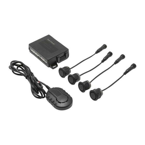
Introduction The PARK-EMCU parking assist system allows you to add rear parking assist to vehicles with plastic bumpers. It comes with an audible alert or can be upgraded with an optional LED display (PARK- LED). The system has simple wiring and comes with everything you need to do the install. -
Page 4: Wiring
Wiring (Main Control Unit) Fuse Purple A B C D Reverse Trigger Speaker (Audible Alert) Black Ground Display (Sold Separately) -
Page 5: Specifications
Specifications OPERATING VOLTAGE 12-16V OPERATING CURRENT DRAW LESS THAN 102mA @12V DETECTION RANGE REAR: 0.3-2.5M/ 1-8.2FT NUMBER OF SENSORS 4 REAR SENSORS PAINTABLE YES, PAINT TRAY INCLUDED AUDIBLE ALERT YES, INCLUDED. ADJUSTABLE VOLUME VISUAL ALERT YES, SOLD SEPERATELY SELF TEST FUNCTION YES... -
Page 6: Key Features
Key Features Key Features: • Visual display – This system comes with an audible alert but there is an optional visual alerts sold separately (PARK-LED). • Self-testing – This system will run a quick diagnostics every time it is powered on. •... -
Page 7: Self Test
Self Test SELF-TEST When the vehicle’s gearshift is placed in “R”, the system will perform a self-test. This will test all of the connected sensors to make sure that they are working as intended. If there are no issues found during this test, the system will give a single audible alert. -
Page 8: Function/ Alerts
Rear System Function Placing the vehicle in Reverse will activate the rear mounted system. - Page 9 Audible Alerts REAR AUDIBLE ALERT Continuous alert <0.3m/1.0ft Faster multiple 0.3~0.6m/1.0~2.0ft repeating alerts Multiple, 0.6~0.9m/2.0~3.0ft repeating alerts Faster, 0.9~1.5m/3.0~5.0ft repeating alert Single, 1.5~2.5m/5.0~8.4ft repeating alert...
-
Page 10: Sensor Installation
Sensor Mounting Instructions SENSOR INSTALLATION: • The mounting height of the sensors should be .45m/1.5’ to .65m/2.1’ . • For optimum performance the sensors should be evenly spaced across the rear of the vehicle with as little curve as possible. •... - Page 11 Sensor Mounting Locations Mark locations before drilling Use tape that will not damage the vehicles paint to mark your sensor locations 45cm/17.75” to 65cm/25.5” Center point of bumper Outer Most Outer Most Optimum Optimum Flat Surface Flat Surface location location to Mount to Mount for Inner...
- Page 12 Drilling the Holes Before drilling any holes, be sure that the hole saw is the same size as the sensors you are installing.
- Page 13 Painting Sensors The sensors come mounted in a paint tray with the rubber “O” rings not installed. This will allow for easy color match paint- After painting the sensors, ing. Once the paint has dried, be sure to install the rubber “O” let them completely dry rings prior to installing the sensors into the vehicle.
-
Page 14: Speaker/ Display Mounting
Mounting the Speaker MOUNTING THE AUDIBLE ALERT REAR MOUNT Recommended speaker placement... - Page 15 Mounting the Display DISPLAY PLACEMENT (optional) The PARK-LED can be added to provide visual feedback when the sensors are triggered. The display is designed to be mounted on the vehicles dash. Dashboard mount...
-
Page 16: Testing
Testing the System - To test the system, use a piece of wood (approx. .3mX1m/ 1’X3.3’). - With the board beyond the furthest trigger point, back up to the board. - The system should trigger once in sensor range. Rear system check... -
Page 17: Troubleshooting
Getting a false warning. A. Are all of the sensors plugged into the main control unit correctly and tightly? B. Do any of the sensors detect the ground? Any other questions should be directed to CrimeStopper technical support at 1-800-998-6880. -
Page 18: French
Câblage (Main Control Unit) Fuse Purple A B C D Reverse Trigger Speaker (Audible Alert) Black Ground Display (Sold Separately) - Page 19 Spécifications TENSION DE FONCTIONNEMENT 12-16V CONSOMMATION DE COURANT DE FONC- MOINS DE 102 mA à 12 V TIONNEMENT PLAGE DE DÉTECTION ARRIÈRE 0,3-2,5 M/ 1-8,2 pi NOMBRE DE DÉTECTEURS 4 ARRIÈRE DÉTECTEURS À PEINDRE OUI, LE BAC À PEINTURE EST INCLUS ALERTE SONORE OUI, INCLUSE VOLUME RÉGLABLE ALERTE VISUELLE OUI, VENDUE SÉPARÉMENT FONCTION D'ESSAI AUTOMATIQUE OUI...
- Page 20 Fonctions clés Fonctions clés : • Affichage visuel – Ce système est muni d'une alarme sonore mais il y a des alarmes visuelles en option venues séparément (PARK-LED). • Test automatique – Ce système procèdera à un diagnostic rapide à chaque fois qu'il est mis sous tension.
- Page 21 Autotest SELF-TEST When the vehicle’s gearshift is placed in “R”, the system will perform a self-test. This will test all of the connected sensors to make sure that they are working as intended. If there are no issues found during this test, the system will give a single audible alert.
- Page 22 Fonction de système arrière Placing the vehicle in Reverse will activate the rear mounted system.
- Page 23 Alertes sonores REAR AUDIBLE ALERT Continuous alert <0.3m/1.0ft Faster multiple 0.3~0.6m/1.0~2.0ft repeating alerts Multiple, 0.6~0.9m/2.0~3.0ft repeating alerts Faster, 0.9~1.5m/3.0~5.0ft repeating alert Single, 1.5~2.5m/5.0~8.4ft repeating alert...
- Page 24 Instructions de montage de détecteurs INSTALLATION DES DÉTECTEURS • La hauteur de montage des détecteurs doit être de 0,45 m/1,5’ à 0,65 m/2,1’ . • Pour une performance optimale, les détecteurs doivent être uniformément espacés sur l'arrière du véhicule avec le moins de courbe possible. •...
- Page 25 Emplacements de montage des détecteurs Mark locations before drilling Use tape that will not damage the vehicles paint to mark your sensor locations 45cm/17.75” to 65cm/25.5” Center point of bumper Outer Most Outer Most Optimum Optimum Flat Surface Flat Surface location location to Mount...
- Page 26 Perçage des trous Before drilling any holes, be sure that the hole saw is the same size as the sensors you are installing.
- Page 27 Peinture des détecteurs Les détecteurs sont livrés montés dans un bac à peinture avec les joints toriques en caoutchouc non installés. Ce qui After painting the sensors, permettra de peindre en assortissant facilement les couleurs. let them completely dry Une fois la peinture sèche, veiller à installer les joints toriques before installing the silicone ring.
- Page 28 Montage du haut-parleur MOUNTING THE AUDIBLE ALERT REAR MOUNT Recommended speaker placement...
- Page 29 Montage de l'affichage DISPLAY PLACEMENT (optional) The PARK-LED can be added to provide visual feedback when the sensors are triggered. The display is designed to be mounted on the vehicles dash. Dashboard mount...
- Page 30 Test du système - To test the system, use a piece of wood (approx. .3mX1m/ 1’X3.3’). - With the board beyond the furthest trigger point, back up to the board. - The system should trigger once in sensor range. Rear system check...
- Page 31 Obtenir un faux avertissement A. Tous les détecteurs sont-ils bien branchés correctement dans la principale unité de contrôle? B. L'un des détecteurs détecte-il la terre ? Toute autre question doit être adressée au support technique CrimeStopper en composant le 1-800- 998-6880.
-
Page 32: Spanish
Cableado (Main Control Unit) Fuse Purple A B C D Reverse Trigger Speaker (Audible Alert) Black Ground Display (Sold Separately) - Page 33 Especificaciones Voltaje de funcionamiento 12-16V CONSUMO DE CORRIENTE EN FUNCIONA- MENOS DE 102 mA a 12 V MIENTO ALCANCE DE DETECCIÓN ATRÁS: 0.3-2.5 M / 1-8.2 PIES CANTIDAD DE SENSORES 4 ATRÁS SENSORES QUE SE PUEDEN PINTAR SI, SE INCLUYE UNA BANDEJA DE PINTURA ALERTA SONORA SI, INCLUIDA VOLUMEN AJUSTABLE ALERTA VISUAL SI, SE VENDE POR SEPARADO...
- Page 34 Características claves Características claves: • Presentación visual – Este sistema viene con una alerta sonora, pero hay una alerta visual opcional que se vende por separado (PARK-LED. • Autocomprobación – Este sistema ejecuta un diagnóstico rápido cada vez que se enciende. •...
- Page 35 Autocomprobación SELF-TEST When the vehicle’s gearshift is placed in “R”, the system will perform a self-test. This will test all of the connected sensors to make sure that they are working as intended. If there are no issues found during this test, the system will give a single audible alert.
- Page 36 Funcionamiento del sistema trasero Placing the vehicle in Reverse will activate the rear mounted system.
- Page 37 Alertas sonoras REAR AUDIBLE ALERT Continuous alert <0.3m/1.0ft Faster multiple 0.3~0.6m/1.0~2.0ft repeating alerts Multiple, 0.6~0.9m/2.0~3.0ft repeating alerts Faster, 0.9~1.5m/3.0~5.0ft repeating alert Single, 1.5~2.5m/5.0~8.4ft repeating alert...
- Page 38 Instrucciones de montaje para el sensor INSTALACIÓN DEL SENSOR • La altura de montaje de los sensores debe ser de 0.45 m / 1.5 pies hasta 0.65 m / 2.1 pies. • Para que se desempeñen de manera óptima, los sensores deben estar espaciados a través de la parte trasera del vehículo con la menor curvatura posible.
- Page 39 Ubicaciones para el montaje del sensor Mark locations before drilling Use tape that will not damage the vehicles paint to mark your sensor locations 45cm/17.75” to 65cm/25.5” Center point of bumper Outer Most Outer Most Optimum Optimum Flat Surface Flat Surface location location to Mount...
- Page 40 Perforación de los agujeros Before drilling any holes, be sure that the hole saw is the same size as the sensors you are installing.
- Page 41 Pintura de los sensores Los sensores vienen montados en una bandeja de pintura con las juntas tóricas ("O" rings) de caucho no instaladas. Esto permitirá pintar para tener una fácil combinación de colores. After painting the sensors, Una vez que la pintura se haya secado, asegúrese de instalar let them completely dry las juntas tóricas de caucho ("O"...
- Page 42 Montaje del altavoz MOUNTING THE AUDIBLE ALERT REAR MOUNT Recommended speaker placement...
- Page 43 Montaje de la pantalla DISPLAY PLACEMENT (optional) The PARK-LED can be added to provide visual feedback when the sensors are triggered. The display is designed to be mounted on the vehicles dash. Dashboard mount...
- Page 44 Prueba del sistema - To test the system, use a piece of wood (approx. .3mX1m/ 1’X3.3’). - With the board beyond the furthest trigger point, back up to the board. - The system should trigger once in sensor range. Rear system check...
- Page 45 Se obtiene una advertencia falsa. A. ¿Están todos los sensores conectados a la unidad de control principal de forma correcta y ajustada? B. ¿Alguno de los sensores detecta el suelo? Se debe dirigir cualquier otra pregunta al apoyo técnico de CrimeStopper al 1-800-998-6880.
-
Page 46: Notes
NOTES... - Page 47 NOTES...
Need help?
Do you have a question about the PARK-EMCU and is the answer not in the manual?
Questions and answers