Shure SCM800 User Manual
Eight-channel microphone mixer
Hide thumbs
Also See for SCM800:
- User manual (12 pages) ,
- User manual (13 pages) ,
- Specification sheet (2 pages)
Table of Contents
Advertisement
Quick Links
SCM800 -- Eight-Channel Microphone Mixer
IMPORTANT SAFETY INSTRUCTIONS
1. READ these instructions.
2. KEEP these instructions.
3. HEED all warnings.
4. FOLLOW all instructions.
5. DO NOT use this apparatus near water.
6. CLEAN ONLY with dry cloth.
7. DO NOT block any ventilation openings. Allow sufficient distances for adequate ventilation and install in accor
dance with the manufacturer's instructions.
8. DO NOT install near any heat sources such as open flames, radiators, heat registers, stoves, or other appara
tus (including amplifiers) that produce heat. Do not place any open flame sources on the product.
9. DO NOT defeat the safety purpose of the polarized or grounding type plug. A polarized plug has two blades
with one wider than the other. A grounding type plug has two blades and a third grounding prong. The wider
blade or the third prong are provided for your safety. If the provided plug does not fit into your outlet, consult an
electrician for replacement of the obsolete outlet.
10. PROTECT the power cord from being walked on or pinched, particularly at plugs, convenience receptacles,
and the point where they exit from the apparatus.
11. ONLY USE attachments/accessories specified by the manufacturer.
12. USE only with a cart, stand, tripod, bracket, or table specified by the manufacturer, or sold with the apparatus.
When a cart is used, use caution when moving the cart/apparatus combination to avoid injury from tip-over.
13. UNPLUG this apparatus during lightning storms or when unused for long periods of time.
14. REFER all servicing to qualified service personnel. Servicing is required when the apparatus has been dam
aged in any way, such as power supply cord or plug is damaged, liquid has been spilled or objects have fallen
into the apparatus, the apparatus has been exposed to rain or moisture, does not operate normally, or has
been dropped.
15. DO NOT expose the apparatus to dripping and splashing. DO NOT put objects filled with liquids, such as vas
es, on the apparatus.
16. The MAINS plug or an appliance coupler shall remain readily operable.
17. The airborne noise of the Apparatus does not exceed 70dB (A).
18. Apparatus with CLASS I construction shall be connected to a MAINS socket outlet with a protective earthing
connection.
19. To reduce the risk of fire or electric shock, do not expose this apparatus to rain or moisture.
20. Do not attempt to modify this product. Doing so could result in personal injury and/or product failure.
1/15
Advertisement
Table of Contents

Related Manuals for Shure SCM800


Summary of Contents for Shure SCM800
-
Page 1: Important Safety Instructions
SCM800 -- Eight-Channel Microphone Mixer IMPORTANT SAFETY INSTRUCTIONS 1. READ these instructions. 2. KEEP these instructions. 3. HEED all warnings. 4. FOLLOW all instructions. 5. DO NOT use this apparatus near water. 6. CLEAN ONLY with dry cloth. 7. DO NOT block any ventilation openings. Allow sufficient distances for adequate ventilation and install in accor... - Page 2 Each SCM800 accepts up to eight microphone or line–level inputs and one auxlevel input (two input jacks feed the same channel). Up to four SCM800 mixers can be linked to provide up to 32 input channels. Each input chan nel has a two-band equalizer, switchable microphone- or line-level operation, switchable 48 V phantom power, and a ¼-inch send/ receive insert jack.
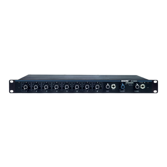
- Page 3 Shure Incorporated SCM800 Front Panel MODEL SCM800/E FRONT PANEL FIGURE 1 1. Microphone Channel Gain Controls 1 - 8: Allows adjustment of microphone gain. 2. Input LED 1 - 8: Lights red at 6 dB below clipping level. 3. Low-Cut Filter 1 - 8: Recessed screwdriver adjustment provides adjustable low-frequency rolloff (high pass) to reduce undesirable low- frequency signals.
-
Page 4: Power Led
The 7-position DIP switch provides control of the output limiter threshold (see DIP Switches). 13. LINK IN/OUT Jacks: Permit multiple SCM800 mixers to be stacked for additional inputs. 14. LINE OUTPUT Removable Block Connector: Active balanced line-level signal for connection to amplifiers, recorders or other mixers. If necessary, output level can be changed to microphone level. -
Page 5: System Setup
Rack mounting the SCM800/E To mount an SCM800 or SCM800E in a standard 483 mm (19-inch) audio equipment rack so that the front panel faces out, as shown in Figure 4. Then secure the mixer to the rack with the four supplied Phillips head screws. -
Page 6: Dip Switch Functions
Shure Incorporated SCM800/E AUDIO CONNECTIONS FIGURE 5 OUTPUT LIMITER THRESHOLD SETTINGS The DIP switches on the rearpanel, shown below in Figure 3, control the output limiter threshold settings. Switch es 5 and 6 change the output limiter threshold to OFF (default setting), +16 dBm, +8 dBm, or +4 dBm. Other set... - Page 7 LINKING MULTIPLE SCM800 MIXERS Up to four SCM800 mixers can be “linked” using the supplied link cables If additional inputs are needed. Such a configuration can provide 32 mic inputs. Refer to Figure 6. When multiple SCM800 mixers are linked, all input sig...
-
Page 8: Basic Mixer Operation
USING AN SCM800 AS A SUBMIXER The master output of the SCM800 (or the output of a mixer in a group of linked SCM800 mixers) can be connected to a channel input or the aux input of an automatic mixer, or other types of mixers. See Figure 8. -
Page 9: Equalizer Functions
The rate at which this attenuation oc curs is defined in decibels per octave (dB/oct). The SCM800 has a one-pole, low-cut (highpass) filter of 6 dB per octave. Lowcut filters are ideally used for attenuating, or rolling off, the audio signal where extraneous noise, ex... -
Page 10: Internal Modifications
Shure Incorporated HIGH-FREQUENCY SHELVING EFFECTS FIGURE 10 Internal Modifications NOTE: Remove AC power before opening the unit. ABOUT PRINTED CIRCUIT BOARD MODIFICATIONS • A jumper is represented by “X” on the printed circuit board legend, a resistor is represented by an “R.”... - Page 11 Shure Incorporated NOTE: To compensate for higher output condenser microphones, the factory-set gain in the PHM position is 13 dB lower than the gain in the MIC position. Line-Level Output to Mic-Level Output Procedure: 1. Short jumper X901. 2. Remove resistors R900 and R909.
-
Page 12: Specifications
For Aux In control: 1. Connect the external source to the VCA line input. 2. Connect the VCA line output to the tip and sleeve of the SCM800 Aux input. 3. Set the Aux control to 5. For Master control: 1. - Page 13 Shure Incorporated Inputs Outputs Total Harmonic Distortion <0.1%at +18 dBVoutput level, 50 Hz to 20 kHz(through 20 Hz-20 kHz filter); Input 1 and Master at 5, all other con trols full counterclockwise) Hum and Noise Equivalent Input Noise -125 dBV(150 Ω source; through 400 Hz-20 kHz fil...
-
Page 14: Replacement Parts
Net Weight 4.3 kg (9 lb ., 9 oz.) Replacement Parts Knob, Channel Gain and Phones (white) 95A8238 Knob, Master (blue) 95B8752 Line (Power) Cord (SCM800) 95B8389 230 VAC Power Line Cord 95B8247 Link Cable 95B8889 Three -Terminal Block Connector... - Page 15 Shure Incorporated Service Statement For additional service or parts information, please contact Shure's Service department at 1-800-516-2525. Outside the United States, please contact your authorized Shure Service Center. Certifications SCM800: Listed by Underwriters Laboratories, Inc.; Certified by Canadian Standards Association; SCM800E: Con...
Need help?
Do you have a question about the SCM800 and is the answer not in the manual?
Questions and answers