Table of Contents
Advertisement
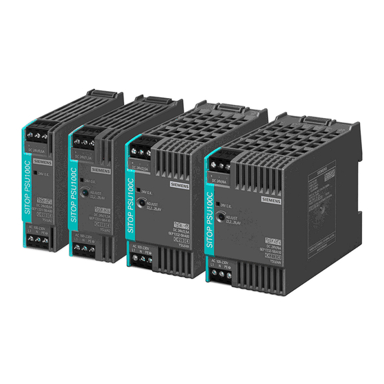
SITOP PSU100C
SITOP power supply
SITOP PSU100C
Operating Instructions
SITOP PSU100C 12 V/2 A
6EP1321-5BA00
SITOP PSU100C 12 V/6.5 A
6EP1322-5BA10
SITOP PSU100C 24 V/0.6 A
6EP1331-5BA00
SITOP PSU100C 24 V/1.3 A
6EP1331-5BA10
SITOP PSU100C 24 V/2.5 A
6EP1332-5BA00
SITOP PSU100C 24 V/3.7 A
6EP1332-5BA20
SITOP PSU100C 24 V/4 A
6EP1332-5BA10
06.2013
C98130-A7599-A1-2-7629
___________________
Overview
___________________
Safety instructions
Description, device design,
___________________
dimension drawing
___________________
Mounting/disassembly
Mounting position, mounting
___________________
clearances
___________________
Installation
___________________
Technical data
___________________
Safety, approvals, EMC
___________________
Ambient conditions
___________________
Applications
___________________
Environment
___________________
Service & Support
1
2
3
4
5
6
7
8
9
10
11
Advertisement
Table of Contents

Related Manuals for Siemens SITOP PSU100C 6EP1321-5BA00


Summary of Contents for Siemens SITOP PSU100C 6EP1321-5BA00
- Page 1 ___________________ SITOP PSU100C Overview ___________________ Safety instructions Description, device design, ___________________ dimension drawing SITOP power supply ___________________ Mounting/disassembly Mounting position, mounting ___________________ SITOP PSU100C clearances ___________________ Installation Operating Instructions ___________________ Technical data ___________________ Safety, approvals, EMC ___________________ Ambient conditions ___________________ Applications ___________________ Environment...
- Page 2 Note the following: WARNING Siemens products may only be used for the applications described in the catalog and in the relevant technical documentation. If products and components from other manufacturers are used, these must be recommended or approved by Siemens. Proper transport, storage, installation, assembly, commissioning, operation and maintenance are required to ensure that the products operate safely and without any problems.
-
Page 3: Overview
Overview The key benefits of the product include: ● Power supply with wide range input for operation on 1-phase AC line supplies or a DC voltage ● Small mounting footprint as a result of the low-profile design ● Low energy usage as a result of the high efficiency over the complete load range ●... - Page 4 Overview Ordering data The following device options are available: SITOP PSU100C primary-clocked power supply Type Order number Input 100 - 230 V AC 6EP1321-5BA00 120 - 230 V DC Output 12 V DC / 2 A Input 100 - 230 V AC 6EP1322-5BA10 120 - 230 V DC Output 12 V DC / 6.5 A...
-
Page 5: Table Of Contents
Table of contents Overview..............................3 Safety instructions ............................. 7 Description, device design, dimension drawing ..................9 Device description..........................9 Connections and terminal designation..................10 Potentiometer..........................11 Operating displays and signaling ....................12 Block diagram ..........................13 Dimensions and weight........................14 Mounting/disassembly ..........................17 Mounting position, mounting clearances....................19 Standard mounting position ......................19 Other mounting positions ......................22 Installation ............................... - Page 6 Table of contents Ambient conditions ..........................45 Applications ............................. 47 Parallel connection to increase the power rating ................ 47 Parallel connection for redundancy..................... 49 Series connection for increased voltage ..................51 Protection against short-time voltage dips .................. 52 Environment ............................53 Service &...
-
Page 7: Safety Instructions
Safety instructions WARNING Correct handling of the devices When operating electrical devices, it is inevitable that certain components will carry dangerous voltages. Therefore, failure to handle the units properly can result in death or serious physical injury as well as extensive property damage. Only appropriately qualified personnel may work on or in the vicinity of this equipment. - Page 8 Safety instructions SITOP PSU100C Operating Instructions, 06.2013, C98130-A7599-A1-2-7629...
-
Page 9: Description, Device Design, Dimension Drawing
Description, device design, dimension drawing Device description SITOP PSU100C are primary clocked power supplies for connection to a 1-phase AC line supply or to DC power systems. An electronically regulated DC voltage that can be set via a potentiometer is available at the output of the device (not for the devices: 6EP1331-5BA00, 6EP1332-5BA20). -
Page 10: Connections And Terminal Designation
Description, device design, dimension drawing 2.2 Connections and terminal designation Connections and terminal designation ① The line input terminals can be used to establish the connection to supply voltage. The ② output terminals are used to connect to the loads to be supplied (see also Section Installation (Page 23)). -
Page 11: Potentiometer
Description, device design, dimension drawing 2.3 Potentiometer Potentiometer ④ The potentiometer on the front of the device is used to adjust the output voltage. The output voltage is set to the rated value at the factory and can be set within certain limits; for example, to compensate voltage drops across long supply lines to the connected load. -
Page 12: Operating Displays And Signaling
Description, device design, dimension drawing 2.4 Operating displays and signaling Operating displays and signaling 6EP1321-5BA00 (12 V/2 A) 6EP1322-5BA10 (12 V/6.5 A) 6EP1331-5BA00 (24 V/0.6 A) 6EP1331-5BA10 (24 V/1.3 A) 6EP1332-5BA00 (24 V/2.5 A) 6EP1332-5BA20 (24 V/3.7 A) 6EP1332-5BA10 (24 V/4 A) Operating display Green LED for output voltage OK Figure 2-4... -
Page 13: Block Diagram
Description, device design, dimension drawing 2.5 Block diagram Block diagram Figure 2-5 Block diagram SITOP PSU100C Operating Instructions, 06.2013, C98130-A7599-A1-2-7629... -
Page 14: Dimensions And Weight
Description, device design, dimension drawing 2.6 Dimensions and weight Dimensions and weight 106,5 22,5 Figure 2-6 Dimension drawing 6EP1331-5BA00 106,5 Figure 2-7 Dimension drawing 6EP1331-5BA10, 6EP1321-5BA00 SITOP PSU100C Operating Instructions, 06.2013, C98130-A7599-A1-2-7629... - Page 15 Description, device design, dimension drawing 2.6 Dimensions and weight 106,5 Figure 2-8 Dimension drawing 6EP1332-5BA00 Figure 2-9 Dimension drawing 6EP1332-5BA20, 6EP1332-5BA10, 6EP1322-5BA10 SITOP PSU100C Operating Instructions, 06.2013, C98130-A7599-A1-2-7629...
- Page 16 Description, device design, dimension drawing 2.6 Dimensions and weight 6EP1331-5BA00 6EP1321-5BA00 6EP1332-5BA00 6EP1322-5BA10 (24 V/0.6 A) (12 V/2 A) (24 V/2.5 A) (12 V/6.5 A) 6EP1331-5BA10 6EP1332-5BA20 (24 V/1.3 A) (24 V/3.7 A) 6EP1332-5BA10 (24 V/4 A) Dimensions 22.5 × 80 × 100 30 ×...
-
Page 17: Mounting/Disassembly
Mounting/disassembly WARNING Installing the device in a housing or a control cabinet SITOP PSU100C power supplies are built-in units. They must be installed in a casing or control cabinet to which only qualified personnel have access. The devices can be mounted in a control cabinet on standard mounting rails according to EN 60715 35x7,5/15. - Page 18 Mounting/disassembly WARNING Use in hazardous zones If the device is to be used in a hazardous zone (Ex II 3G Ex nA IIC T4 Gc) it must be installed in a distribution box with degree of protection IP54 or higher. SITOP PSU100C Operating Instructions, 06.2013, C98130-A7599-A1-2-7629...
-
Page 19: Mounting Position, Mounting Clearances
Mounting position, mounting clearances Standard mounting position The device is mounted on standard mounting rails according to EN 60715 35x7,5/15. The device must be mounted vertically in such a way that the input terminals are at the bottom and the output terminals are at the top to ensure correct cooling. A clearance of at least 50 mm must always be maintained above and below the device. - Page 20 Mounting position, mounting clearances 4.1 Standard mounting position Figure 4-2 6EP1321-5BA00: Output current in the standard mounting position Figure 4-3 6EP1322-5BA10: Output current in the standard mounting position Figure 4-4 6EP1331-5BA00: Output current in the standard mounting position SITOP PSU100C Operating Instructions, 06.2013, C98130-A7599-A1-2-7629...
- Page 21 Mounting position, mounting clearances 4.1 Standard mounting position 1.25 0.75 0.25 Figure 4-5 6EP1331-5BA10: Output current in the standard mounting position Figure 4-6 6EP1332-5BA00: Output current in the standard mounting position Figure 4-7 6EP1332-5BA20: Output current in the standard mounting position SITOP PSU100C Operating Instructions, 06.2013, C98130-A7599-A1-2-7629...
-
Page 22: Other Mounting Positions
Mounting position, mounting clearances 4.2 Other mounting positions Figure 4-8 6EP1332-5BA10: Output current in the standard mounting position 1000 2000 3000 4000 5000 6000 -1000 Figure 4-9 Mounting height derating For details, see Section Ambient conditions (Page 45) Other mounting positions Not permitted. -
Page 23: Installation
Installation WARNING Hazard due to electric shock Before installation or maintenance work can begin, the system's main switch must be switched off and measures taken to prevent it being switched on again. If this instruction is not observed, touching live parts can result in death or serious injury. Line-side connection SITOP PSU100C power supplies are designed for connection to 1-phase AC line supplies (TN or TT system according to VDE 0100 T 300 / IEC 364-3) with a rated voltage of 1-phase... - Page 24 Installation 5.1 Line-side connection Protection SITOP PSU100C Recommended line-side protection 6EP1321-5BA00 (12 V/2 A) Miniature circuit-breaker (IEC 898): Characteristic B from 16 A and higher or characteristic C from 10 A 6EP1322-5BA10 Miniature circuit-breaker (IEC 898): Characteristic B from 16 A and higher or characteristic (12 V/6.5 A) C from 10 A 6EP1331-5BA00...
-
Page 25: Output-Side Connection
Installation 5.2 Output-side connection Output-side connection The SITOP PSU100C power supplies provide an isolated (= non-grounded) SELV (Safety Extra Low Voltage) output voltage. The output of the power supplies is no-load, overload and short-circuit proof. If an overload occurs, the electronic current limiting function limits the output current to a maximum value (refer to Chapter Technical data (Page 27)). - Page 26 Installation 5.2 Output-side connection SITOP PSU100C Operating Instructions, 06.2013, C98130-A7599-A1-2-7629...
-
Page 27: Technical Data
Technical data Note For an AC input voltage, the technical data is applicable for rated input voltage, rated load and +25° C ambient temperature (if nothing else is specified). Input 6EP1321-5BA00 6EP1322-5BA10 6EP1331-5BA00 6EP1331-5BA10 (12 V/2 A) (12 V/6.5 A) (24 V/0.6 A) (24 V/1.3 A) Input... - Page 28 Technical data 6.1 Input 6EP1332-5BA00 6EP1332-5BA20 6EP1332-5BA10 (24 V/2.5 A) (24 V/3.7 A) (24 V/4 A) Input 1-phase AC or DC Rated voltage e rated / for 100...230 V Voltage range / for AC 85...264 V Rated voltage Ue rated / for 120...230 V Voltage range / for DC 110…300 V...
-
Page 29: Output
Technical data 6.2 Output Output 6EP1321-5BA00 6EP1322-5BA10 6EP1331-5BA00 6EP1331-5BA10 (12 V/2 A) (12 V/6.5 A) (24 V/0.6 A) (24 V/1.3 A) Output Regulated, isolated DC voltage Rated voltage value Ua rated DC 12 V 12 V 24 V 24 V Total tolerance, static ±... - Page 30 Technical data 6.2 Output 6EP1332-5BA00 6EP1332-5BA20 6EP1332-5BA10 (24 V/2.5 A) (24 V/3.7 A) (24 V/4 A) Output Regulated, isolated DC voltage Rated voltage value Ua rated DC 24 V Total tolerance, static ± Static line regulation, approx. 0.1 % 0.1 % 0.1 % Static load regulation, approx.
- Page 31 Technical data 6.2 Output Figure 6-2 Startup delay/voltage rise 12.5 12V / 2A 12V / 6,5A Figure 6-3 12 V output characteristic 24V / 4A 24V / 1.3A 24V / 2.5A 24V / 3.7A 24V / 0.6A Figure 6-4 24 V output characteristic SITOP PSU100C Operating Instructions, 06.2013, C98130-A7599-A1-2-7629...
-
Page 32: Efficiency And Power Loss
Technical data 6.3 Efficiency and power loss The device supplies a constant output voltage until the current limit is reached. In the event of an overload, the output current and the output voltage are reduced. When the output voltage falls below approx. 9 V (12 V versions) and 15 V (24 V versions), the device switches off, and automatically restarts. - Page 33 Technical data 6.3 Efficiency and power loss Figure 6-6 Efficiency for AC: 6EP1322-5BA10 Figure 6-7 Efficiency for AC: 6EP1331-5BA00 SITOP PSU100C Operating Instructions, 06.2013, C98130-A7599-A1-2-7629...
- Page 34 Technical data 6.3 Efficiency and power loss Figure 6-8 Efficiency for AC: 6EP1331-5BA10 Figure 6-9 Efficiency for AC: 6EP1332-5BA00 SITOP PSU100C Operating Instructions, 06.2013, C98130-A7599-A1-2-7629...
- Page 35 Technical data 6.3 Efficiency and power loss Figure 6-10 Efficiency for AC: 6EP1332-5BA20 Figure 6-11 Efficiency for AC: 6EP1332-5BA10 SITOP PSU100C Operating Instructions, 06.2013, C98130-A7599-A1-2-7629...
-
Page 36: Closed-Loop Control
Technical data 6.4 Closed-loop control Closed-loop control 6EP1321-5BA00 6EP1322-5BA10 6EP1331-5BA00 6EP1331-5BA10 (12 V/2 A) (12 V/6.5 A) (24 V/0.6 A) (24 V/1.3 A) Dyn. line compensation 0.1 % 0.1 % 0.1 % 0.1 % (Ue rated ±15%), max. Dyn. load compensation (Ia: 10/90/10 %), Ua ±... -
Page 37: Protection And Monitoring
Technical data 6.5 Protection and monitoring Protection and monitoring 6EP1321-5BA00 6EP1322-5BA10 6EP1331-5BA00 6EP1331-5BA10 (12 V/2 A) (12 V/6.5 A) (24 V/0.6 A) (24 V/1.3 A) Output overvoltage protection Yes, according to EN 60950-1 Current limitation, typ. 2.4 A 7.2 A 0.7 A 1.4 A Property of the... - Page 38 Technical data 6.7 Mechanical system 6EP1321-5BA00 6EP1322-5BA10 6EP1331-5BA00 6EP1331-5BA10 (12 V/2 A) (12 V/6.5 A) (24 V/0.6 A) (24 V/1.3 A) Width of the housing 30 mm 52.5 mm 22.5 mm 30 mm Height of the housing 80 mm 80 mm 80 mm 80 mm Depth of the housing...
-
Page 39: Accessories
6EP1332-5BA20 (24 V/3.7 A) 6EP1332-5BA10 (24 V/4 A) Mechanical accessories Removable 6EP1971-5BA00 spring-loaded terminal Dimension drawing See Section Dimensions and weight (Page 14) CAD data that can be downloaded from the Internet: 6EP1321-5BA00 (http://www.automation.siemens.com/bilddb/index.aspx?objKey=G_KT01_XX_00411) 6EP1322-5BA10 (http://www.automation.siemens.com/bilddb/index.aspx?objKey=G_KT01_XX_00468) 6EP1331-5BA00 (http://www.automation.siemens.com/bilddb/index.aspx?objKey=G_KT01_XX_00415) 6EP1331-5BA10 (http://www.automation.siemens.com/bilddb/index.aspx?objKey=G_KT01_XX_00419) 6EP1332-5BA00 (http://www.automation.siemens.com/bilddb/index.aspx?objKey=G_KT01_XX_00462) -
Page 41: Safety, Approvals, Emc
Safety, approvals, EMC Safety 6EP1321-5BA00 (12 V/2 A) 6EP1322-5BA10 (12 V/6.5 A) 6EP1331-5BA00 (24 V/0.6 A) 6EP1331-5BA10 (24 V/1.3 A) 6EP1332-5BA00 (24 V/2.5 A) 6EP1332-5BA20 (24 V/3.7 A) 6EP1332-5BA10 (24 V/4 A) Primary/secondary galvanic isolation Galvanic isolation SELV output voltage Ua according to EN 60950-1 and EN 50178 Transformer according to EN 61558-2-16 Protection class Class I... -
Page 42: Test Voltage
Safety, approvals, EMC 7.2 Test voltage Test voltage Figure 7-1 Test voltage diagram Only the manufacturer can perform the type test and production test; users can also perform the field test. Preconditions for performing the field test: Tests (A) & (B) ●... -
Page 43: Certifications
Safety, approvals, EMC 7.3 Certifications Certifications 6EP1321-5BA00 6EP1322-5BA10 6EP1331-5BA00 6EP1331-5BA10 (12 V/2 A) (12 V/6.5 A) (24 V/0.6 A) (24 V/1.3 A) CE marking UL/CSA approval UL/cUL (CSA) approval cULus-Listed (UL 508, CSA C22.2 No. 107.1), File E197259; cCSAus (CSA C22.2 No. 60950- 1, UL 60950-1) NEC Class 2 Output limited to... -
Page 44: Emc
Safety, approvals, EMC 7.4 EMC 6EP1321-5BA00 (12 V/2 A) 6EP1322-5BA10 (12 V/6.5 A) 6EP1331-5BA00 (24 V/0.6 A) 6EP1331-5BA10 (24 V/1.3 A) 6EP1332-5BA00 (24 V/2.5 A) 6EP1332-5BA20 (24 V/3.7 A) 6EP1332-5BA10 (24 V/4 A) Electrostatic discharge EN 61000-4-2 8 kV contact, 8 kV air Electromagnetic fields EN 61000-4-3 0.15…80 MHz 10 V/m, 80…1000 MHz 20 V/m... -
Page 45: Ambient Conditions
Ambient conditions 6EP1322-5BA10 (12 V/6.5 A) 6EP1321-5BA00 (12 V/2 A) 6EP1332-5BA00 (24 V/2.5 A) 6EP1331-5BA00 (24 V/0.6 A) 6EP1332-5BA20 (24 V/3.7 A) 6EP1331-5BA10 (24 V/1.3 A) 6EP1332-5BA10 (24 V/4 A) Ambient temperature -20...+70° C with natural convection -20...+70° C with natural convection from +50 °C: 3.5 % Ia rated/K from +55 °C: 3 % Ia rated/K ... - Page 46 Ambient conditions 6EP1322-5BA10 (12 V/6.5 A) 6EP1321-5BA00 (12 V/2 A) 6EP1332-5BA00 (24 V/2.5 A) 6EP1331-5BA00 (24 V/0.6 A) 6EP1332-5BA20 (24 V/3.7 A) 6EP1331-5BA10 (24 V/1.3 A) 6EP1332-5BA10 (24 V/4 A) Damaging gases Tested according to: EN 60068-2-42 Sulfur dioxide: 10cm , 4 days ...
-
Page 47: Applications
Applications Parallel connection to increase the power rating To increase the power rating, two identical power supplies SITOP PSU100C, with the exception of 6EP1331-5BA00 and 6EP1332-5BA20, can be directly connected with one another galvanically. The following must be observed: ● The output voltages of the power supplies to be connected in parallel may differ by a maximum of 0.2 % under no load conditions. - Page 48 Applications 9.1 Parallel connection to increase the power rating NOTICE Protective circuit for the parallel connection of more than two power supplies When connecting more than two power supplies in parallel, additional measures must be taken to prevent high reverse currents in the event of a secondary device fault. For this purpose, a suitable protective circuit (e.g.
-
Page 49: Parallel Connection For Redundancy
Applications 9.2 Parallel connection for redundancy Parallel connection for redundancy Connecting several SITOP PSU100C power supplies in parallel for redundancy purposes is required if especially high demands are placed on the availability of a reliable 24 V power supply. Using the SITOP PSE202U redundancy module, two 24 V power supplies of the same type can be decoupled (Figure 9-2 Redundant configuration (Page 49)). - Page 50 Applications 9.2 Parallel connection for redundancy Figure 9-3 Parallel connection with redundancy module for NEC Class 2 You can find additional information at: SITOP PSE202U manual (http://support.automation.siemens.com/WW/view/en/42248598) SITOP PSU100C Operating Instructions, 06.2013, C98130-A7599-A1-2-7629...
-
Page 51: Series Connection For Increased Voltage
Applications 9.3 Series connection for increased voltage Series connection for increased voltage To achieve an output voltage of 48 V DC, two SITOP PSU100C power supplies of the same type can be connected in series. In this case, connect the "-" terminal of the first power supply to the "+"... -
Page 52: Protection Against Short-Time Voltage Dips
Applications 9.4 Protection against short-time voltage dips Protection against short-time voltage dips During a drop in the primary-side supply voltage, SITOP PSU100C power supplies still maintain the output voltage over a short millisecond period (see section Technical data, Input (Page 27)) SITOP PSU100C Operating Instructions, 06.2013, C98130-A7599-A1-2-7629... -
Page 53: Environment
Environment The device is in conformance with RoHS. As a rule, only non-silicon precipitating materials are used. Disposal guidelines Packaging and packaging aids can and should always be recycled. The product itself may not be disposed of as domestic refuse. SITOP PSU100C Operating Instructions, 06.2013, C98130-A7599-A1-2-7629... - Page 54 Environment SITOP PSU100C Operating Instructions, 06.2013, C98130-A7599-A1-2-7629...
-
Page 55: Service & Support
● Phone: + 49 (0) 911 895 7222 ● E-Mail (mailto:support.automation@siemens.com) ● Internet: Online support request form (http://www.siemens.de/automation/support-request) Technical documentation on the Internet Operating instructions and manuals for SITOP are available in the Internet: Operating instructions/manuals (http://www.siemens.de/sitop/manuals) SITOP power supply homepage General news about our power supplies is available in the Internet at the SITOP homepage: SITOP (http://www.siemens.de/sitop) - Page 56 Service & Support Contact persons If you have any questions regarding the use of our products, then contact the Siemens contact person in your regional Siemens sales office. You can find these addresses as follows: ● On the Internet (http://www.siemens.de/automation/partner) ●...
Need help?
Do you have a question about the SITOP PSU100C 6EP1321-5BA00 and is the answer not in the manual?
Questions and answers