Table of Contents
Advertisement
Quick Links
SEPTEMBER 2018
™
VesseLINK
User Manual
This document contains technology controlled for export by the U.S. Department of
Commerce in accordance with Export Administration Regulations. Diversion contrary to
U.S. law prohibited.
i
User Manual PN 84469 Rev B
COPYRIGHT © 2018
THALES DEFENSE & SECURITY, INC.
ALL RIGHTS RESERVED
Advertisement
Table of Contents

Subscribe to Our Youtube Channel
Related Manuals for Thales VesseLINK


Summary of Contents for Thales VesseLINK
- Page 1 This document contains technology controlled for export by the U.S. Department of Commerce in accordance with Export Administration Regulations. Diversion contrary to U.S. law prohibited. User Manual PN 84469 Rev B COPYRIGHT © 2018 THALES DEFENSE & SECURITY, INC. ALL RIGHTS RESERVED...
- Page 2 RECORD OF CHANGES Date Description of Change Author Rev A June 2018 Initial Release SJacques Rev B Sept 2018 ECN: 42154 SJacques • Update based on Beta user feedback and Testing WARNING – INFORMATION SUBJECT TO EXPORT CONTROL RESTRICTIONS WARNING – INFORMATION SUBJECT TO EXPORT CONTROL RESTRICTIONS WARNING –...
- Page 3 No title to or ownership of any proprietary rights related to any Product is transferred to User or any Customer pursuant to the use of this product. The purchase of any Thales products shall not be deemed to grant either directly or by implication or otherwise, any license under copyrights, patents, or patent applications of Thales or any third party software providers, except for the normal, nonexclusive, royalty free license to use that arises by operation of law in the sale of a product.
-
Page 4: Table Of Contents
..........................2-1 ESCRIPTION Below Deck Unit (BDU) ...................... 2-4 Antenna Unit ........................2-7 GETTING STARTED ................... 3-1 ........................3-1 ETTING TARTED THALES MANAGEMENT PORTAL ............4-1 ............4-1 ETTING TO NOW THE HALES ANAGEMENT ORTAL Menu Components ....................... 4-3 Main Dashboard ........................4-7 Status ............................ - Page 5 ACRONYMS / GLOSSARY ................. 8-1 ......................8-1 CRONYMS LOSSARY SPARE PARTS ....................9-1 SPARE PARTS ........................9-1 INDEX ..........................I NDEX List of Figures 1-1 E ......1-2 IGURE ARTH SHOWING RIDIUM SATELLITES IN SIX DEFINED ORBITAL PLANES 1-2 T .
- Page 6 D 4-23 S ....................... 4-19 IGURE ETTINGS ISTRESS S 4-24 S ..................4-20 IGURE ETTINGS ATELLITE CREEN W 4-25 S ....................4-22 IGURE ETTINGS CREEN LAN S 4-26 S ....................4-24 IGURE ETTINGS CREEN WAN S 4-27 S ....................
- Page 7 List of Tables 2-1 B (BDU) LED S ................2-5 ABLE ELOW TATUS 3-1 T IP P .................. 3-2 ABLE YPICAL HONE ONFIGURATION 3-2 B (BDU) LED S ................3-5 ABLE ELOW TATUS 4-1 Q ........................4-4 ABLE UICK CONS ™...
- Page 8 SAFETY ™ The VesseLINK system should only be installed by a qualified professional installer of Maritime electronic systems. Improper installation could lead to system failure or could result in injury to personnel on board the vessel. The following are general safety precautions and warnings that all personnel must read and understand prior to installation, operation and maintenance of the ™...
- Page 9 ANTENNA RADIATION HAZARDS To comply with FCC Radio Frequency radiation exposure limits, the antenna must be installed at a minimum safe distance as shown below. WARNING During operation, the antenna radiates high power at microwave frequencies that can be harmful to individuals. While the unit is operating, personnel should maintain a minimum safe distance of 1.5 meters (4.9 ft.) from the antenna.
- Page 10 FCC INFORMATION FCC Identifier: OKCVF350BM Contains FCC ID: QOQWF121 NOTE Changes or modifications not expressly approved by the manufacturer could void the user’s authority to operate the equipment. Note: This equipment has been tested and found to comply with the limits for a Class B digital device, pursuant to part 15 of the FCC Rules.
- Page 11 Industry Canada Information Industry Canada: 473C-VF350BM Contains IC: 5123A-BGTWF121 NOTE Under Industry Canada regulations, this radio transmitter may only operate using an antenna of a type and maximum (or lesser) gain approved for the transmitter by Industry Canada. To reduce potential radio interference to other users, the antenna type and its gain should be so chosen that the equivalent isotropically radiated power (e.i.r.p.) is not more than that necessary for successful communication.
- Page 12 User Manual PN 84469 Rev B...
-
Page 13: Introduction
™ VesseLINK system. It, however, cannot cover all topics and advanced features. For questions or topics that are not covered in this manual please contact your airtime provider or Thales at www.Thalesdsi.com. THE IRIDIUM SATELLITE NETWORK The Iridium satellite network is comprised of 66 low-earth orbiting (LEO), cross-linked satellites, providing voice and data coverage over Earth’s entire surface. -
Page 14: Figure 1-1 Earth Showing Iridium Satellites In Six Defined Orbital Planes
Figure 1-1 Earth showing Iridium satellites in six defined orbital planes. ™ Figure 1-2 shows a typical flow over the Iridium network of a call made from the VesseLINK system. ™ A VesseLINK voice or data call is sent to the closest satellite overhead that has a high signal strength. -
Page 15: System Overview
SYSTEM OVERVIEW DESCRIPTION ™ ™ The Thales VesseLINK system operates using Iridium Certus broadband services over a network of 66 satellites that cover 100% of the globe, including remote locations and the poles. The solution and essential voice, text and utilizes this robust network service to provide highly reliable, mobile web communications. -
Page 16: Figure 2-2 Local Communications Via Pbx Functionality
• Least Cost Routing automatically routes the data to an optional, lower cost network (i.e., cellular, Wi-Fi, etc.). • Custom Thales softphone application available from the Apple Store and Google Play for use on iOS and Android devices. • Low profile, IP67 rated antenna with single RF cable to the Below Deck Unit (BDU). -
Page 17: Figure 2-3 Thales Vesselink System With Accessories
Figure 2-3. A cellular modem can be connected to the WAN port for data least-cost routing operations. Voice calls are always routed through the Iridium system. ™ Figure 2-3 Thales VesseLINK System with Accessories User Manual PN 84469 Rev B... -
Page 18: Below Deck Unit (Bdu)
Below Deck Unit (BDU) The Below Deck Unit (BDU) supports voice and data communications in a marine environment. The BDU is capable of supporting wireless voice and data that links the user with the Iridium satellite network. As a wireless access point, the BDU provides Wi-Fi (802.11) access for data and Voice over IP (VoIP) calls. -
Page 19: Table 2-1 Below Deck Unit (Bdu) Led Status
Table 2-1 Below Deck Unit (BDU) LED Status Indicator Description System Solid GREEN System functioning properly Flashing GREEN System busy (Booting up) Solid RED Fault (minor issue) Flashing RED Critical fault (major issue) Satellite Solid BLUE Connected and passing data (over satellite) Solid GREEN System functioning properly Flashing GREEN... -
Page 20: Figure 2-6 Below Deck Unit (Bdu) Front Panel Detail
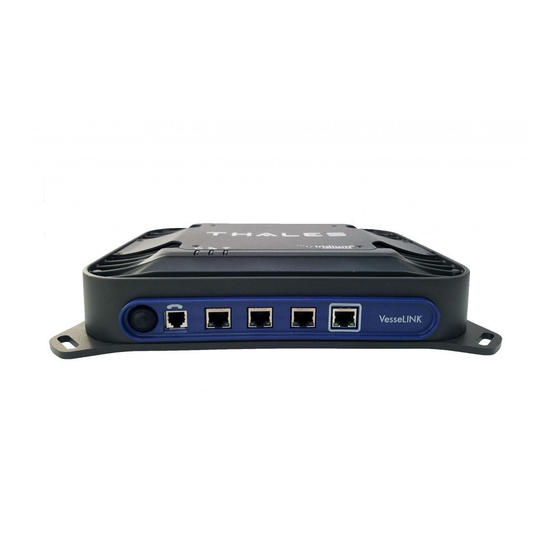
The BDU front panel (left to right) has a main power button, one RJ-14 jack for POTS (Plain Old Telephone Service) Phone(s), three PoE (Power over Ethernet) RJ-45 connections for VoIP phones or Ethernet-based devices, and one WAN (Wide Area Network) connection primarily used to connect an external cellular modem or VSAT. -
Page 21: Antenna Unit
Antenna Unit The Above Deck Unit (ADU) or Antenna is a standalone unit that connects to the BDU through a single coaxial cable. DC power, RF transmit and receive signals, control data and GPS data are communicated between the ADU and BDU using this single coaxial cable. Figure 2-8 Above Deck Unit (ADU) / Antenna Unit User Manual PN 84469 Rev B... - Page 22 THIS PAGE INTENTIONALLY LEFT BLANK User Manual PN 84469 Rev B...
-
Page 23: Getting Started
VoIP or Thales SureLINK IP Phone connection By default the BDU has (3) extensions preconfigured for use with POTS phones, VoIP phones, or the Thales SureLINK IP Handsets as shown in Table 3-1. If using a VoIP phone, Thales recommends CISCO SPA504G and Grand Stream ™... -
Page 24: Figure 3-2 Vesse Link ™ Imei And Imsi From Mobile Device
™ STEP 2: Know your VesseLINK ™ It may be necessary to know details about your VesseLINK system when calling for help or service. IMEI is unique to each unit and can be found on the back plate of the BDU. This IMEI can also be found in the http://portal.thaleslink... -
Page 25: Figure 3-4 Installing Sim Card And Engaging The Lock
STEP 3: Install SIM 1. Open the SIM Card protective cover by pulling it away from the BDU exposing the SIM card slot. (Figure 3-3). Figure 3-3 SIM Card with Cover Opened 2. Install SIM card from Air-time provider (1, Figure 3-4), by inserting the card with contacts down (2) until it clicks into place (3). -
Page 26: Figure 3-5 Secure The Sim Card Cover
(Figure 3-5) Figure 3-5 Secure the SIM Card Cover ™ STEP 4: Power the VesseLINK Unit. Before powering the unit, make sure the DC power cable is connected to a 10-32VDC source, the polarity is correct, and the DC cable is securely connected to the BDU. The antenna must also be connected per the installation manual. -
Page 27: Table 3-2 Below Deck Unit (Bdu) Led Status
Solid RED Fault (minor issue) Flashing RED Critical fault (major issue) ™ STEP 5: Connect to VesseLINK portal to configure system. Reference Figure 3-7. There are a couple options to login to the Management Portal. Option A: Via Wi-Fi. ™... -
Page 28: Figure 3-7 Vesselink User Interface Login
1. Power on the VesseLINK BDU and let it boot up (may take a few minutes) 2. Via the network settings on your computer’s operating system, enable the VesseLINK connection. 3. Open a web browser and type: http://portal.thaleslink (do not type .com or any other extension) 4. -
Page 29: Alert
STEP 6: Place a phone call. The VesseLINK system contains Private Branch Exchange (PBX) functionality, where both local calls and outside calls can be made. Local extensions can be dialed directly from another NOTE local phone, but outside calls require dialing a “9” in order to connect to an outside line prior to dialing the phone number. - Page 30 THIS PAGE INTENTIONALLY LEFT BLANK User Manual PN 84469 Rev B...
-
Page 31: Thales Management Portal
Iridium network. The Thales Management Portal is resident on the TU and can be accessed and viewed on almost any smart device or computer including phones, tablets, laptops, desktop computers, and the optional Thales SureLINK IP Handset. - Page 32 BDU for the first time. When you first enter into the Thales Management Portal, menu items appear on the left side of the screen (see Figure 4-1). Each of these menu items is discussed in the following sections. A short description of each menu item is below.
-
Page 33: Menu Components
• About – Provides system level information for the antenna, modem, power supply, system, VoIP Module, and Wi-Fi. • Help – Provides a link to the VesseLINK ™ User Documentation (Users Guide, Installation Instructions, and Quick Start Guide (QSG)). -
Page 34: Figure 4-2 Quick Link - System Status
Table 4-1 Quick Link Icons ICON Description System Status Satellite Status Wi-Fi Status LAN 1, 2, and 3 Status WAN Status Signal Strength • System Status – The System Status icon provides a quick view of the state of the system. It mirrors the status of the System LED on the BDU. -
Page 35: Figure 4-3 Quick Link - Satellite Status
• Wi-Fi Status – The Wi-Fi Status icon provides a quick view of the Wi-Fi status. It mirrors the Wi-Fi LED on the BDU. Selecting the Wi-Fi Status icon displays the ™ “Connected User Count” (number of users connected to the VesseLINK Wi-Fi) and allows an administrator to ENABLE / DISABLE the Wi-Fi connection. Changes will only take effect once SAVE CHANGES is selected. -
Page 36: Figure 4-5 Quick Link - Lan 1 Status (Lan 2 And Lan 3 Similar)
• LAN Status Icons – The LAN Status icons (LAN 1, LAN 2 and LAN 3) provide a quick view of each LAN’s Status. Each LAN icon is highlighted in blue when a device is plugged into it. By selecting a LAN icon, the additional information in Figure 4-5 is shown, displaying the “Link Status”... -
Page 37: Main Dashboard
The Dashboard also appears by selecting the top menu item highlighted in blue in Figure 4-7. From the Dashboard, you can see information relating to: • Current Alerts • Services ™ Figure 4-7 Thales VesseLINK Dashboard - Main Screen ™ Table 4-2 Thales VesseLINK Dashboard - Main Screen... -
Page 38: Status
Status The STATUS selection screens (CURRENT DEVICE, GPS, LAN, PHONES, SERVICES and SIM) provide information only, and cannot be edited. NOTE Current Devices: Displays all devices currently connected to the Below Deck Unit (BDU), both wired and via Wi- Fi. Wi-Fi CLIENTS list shows the MAC Address, Hostname and IP Address for the current Wi- Fi connected devices. -
Page 39: Figure 4-9 Status Gps Screen
From the GPS page, the operator will have access to detailed GPS information as shown in Figure 4-9. Figure 4-9 Status GPS Screen The LAN page displays the connection status of the built-in Wi-Fi access point and the LAN ports as shown in Figure 4-10. -
Page 40: Figure 4-11 Status Phones Screen
Phones The Phone page provides a list of the registered phones that are connected to the system, including the extension that was assigned as shown in Figure 4-11. Figure 4-11 Status PHONES Screen 4-10 User Manual PN 84469 Rev B... -
Page 41: Figure 4-12 Status Services Screen
Services The Services page provides the status of Satellite and WAN networks, and the current data route as shown in Figure 4-12. Figure 4-12 Status SERVICES Screen 4-11 User Manual PN 84469 Rev B... -
Page 42: Figure 4-13 Status Sim Screen
The SIM page (Figure 4-13) provides the following information: • SIM Info – Status of the SIM card, and its Unique IMSI ID number. The max data rate ™ shows the Certus service level that the SIM card is provisioned to. •... -
Page 43: Alerts
Alerts The ALERTS screen displays a list of active Alerts from the system. If no alerts exist, the alert screen will indicate that there are no active alerts. (Figure 4-14) Figure 4-14 ALERTS Screen (Example Shown with No Active Alerts) For additional information, refer to Chapter 6 Troubleshooting NOTE Alerts may be generated from a Power-On Self-Test (POST) or during normal operation of the... -
Page 44: Calls
Calls Selecting the Calls menu item (Figure 4-16) provides the call logs for active and past calls. Figure 4-16 Call Log Screen Under CALL LOG MANAGEMENT (Figure 4-17), the operator can CLEAR the call log by selecting CLEAR LOG and then confirming by selecting YES, CLEAR LOG.. Figure 4-17 CLEAR Call Log CALL HISTORY displays the last 100 calls that were made. -
Page 45: Distress
Distress Distress Messages can only be configured by the administrator. If the user is not logged in as ADMIN and selects MANAGE DISTRESS, the user will see icon, indicating this function is NOTE not available. The Distress Message (Figure 4-18) menu item allows for enabling and sending a distress email message. -
Page 46: Settings
NOTE Distress menu item. A distress phone call can be made by using the optional Thales SureLINK IP Handset. Configuration of the phone number to be called, as well as, the activation and cancellation of the call takes NOTE place on the handset itself. -
Page 47: Figure 4-21 Settings General Screen
It is always recommended that passwords be changed from defaults for added protection and security. NOTE Figure 4-21 Settings General Screen Table 4-3 Settings General Settings Section Parameters • Select User, Currently there are 3 choices (Admin, Change Password WAN_Admin, and WAN_User) •... - Page 48 Distress Distress messages can only be configured by the administrator. If the user is not logged in as ADMIN and selects MANAGE DISTRESS, the user will see this icon, indicating this NOTE function is not available. Login in as the ADMIN to continue. On the Distress page, the admin can set up a Distress message.
-
Page 49: Distress (Disabled View )
Figure 4-23 Settings Distress Table 4-4 Settings Distress Section Parameters Service Select either Email or OFF (OFF is the default setting) Host Enter the host name (example: smtp.gmail.com) Port Enter the port number (example: 587) TLS Required Select either YES or NO (YES is the default setting) Login Required Select either YES or NO (YES is the default setting) User... -
Page 50: Figure 4-24 Settings Satellite Screen
Figure 4-24 Settings Satellite Screen 4-20 User Manual PN 84469 Rev B... - Page 51 Table 4-5 Settings Satellite Section Value Domain Whitelist & BlackList Domain Blocking OFF / Blacklist / Whitelist (OFF is the default setting) Mode Blacklisting Enabling allows ALL websites EXCEPT those listed (very little restriction) Whitelisting Enabling blocks ALL websites EXCEPT those listed (the most restriction) Port Blocking Port Blocking...
- Page 52 Wireless The Wireless page shown in Figure 4-25 allows setup of the Wi-Fi service. Figure 4-25 Settings Wi-Fi Screen Table 4-6 Settings Wi-Fi Section Value Wireless General Enable Wi-Fi Disabled / Enabled (Enabled is the default setting) SSID Enter the name of the SSID.
- Page 53 Once the initial Wi-Fi WPA2 Security Key is entered, it can be changed at any time by just overwriting the current Security Key in the SETTINGS Wi-Fi WIRELESS GENERAL area. NOTE To identify a device’s MAC address for whitelisting, you should be able to find it in your device’s Settings menu.
- Page 54 Figure 4-26 Settings LAN Screen Table 4-7 Settings Section Value Enable PoE 1 Disabled / Enabled (Enabled is the default setting) Enable PoE 2 Disabled / Enabled (Enabled is the default setting) Enable PoE 3 Disabled / Enabled (Enabled is the default setting) DHCP Enable DHCP Disabled / Enabled (Enabled is the default setting)
- Page 55 This is an ADMIN function only. If the user sees this icon, login as the ADMIN to continue. Otherwise this is a view only screen. NOTE The WAN page, shown in Figure 4-27allows configuration of the WAN data service. The settings include configuring whitelists and blacklists for domains, configuring port blocking and port whitelists.
- Page 56 Figure 4-27 Settings WAN Screen Table 4-8 Settings Section Value Configuration Polling Intervals Sets the length of polling intervals, 30 is the default setting ™ Hostname Lists the Hostname. Certus is the default setting. Mode Select DHCP or Static. (DHCP is the default setting.) Domain Whitelist &...
- Page 57 Phone This is an ADMIN functional only. If the user sees this icon, login as the ADMIN to continue. Otherwise this is a view only screen. NOTE The Phone Settings page, shown in Figure 4-28, allows configuration of phone extensions and mapping of those extensions to the outbound Iridium phone lines as well as which extension rings for each inbound Iridium line.
-
Page 58: Figure 4-28 Settings Phone Screen
Figure 4-28 Settings Phone Screen 4-28 User Manual PN 84469 Rev B... - Page 59 Table 4-9 Settings Phone Section Value Extension Mapping Additional custom extension s of varying lengths can be added. Extension numbers must start with a digit 1-8. 1001 Default extension that receives and makes calls on the first Iridium line. Connected to the first POTS line. 1002 Default extension that receives and makes calls on the second Iridium line.
-
Page 60: Figure 4-29 Settings Radio Gateway
Figure 4-29 Settings Radio Gateway 4-30 User Manual PN 84469 Rev B... - Page 61 Table 4-10 Settings Radio Gateway Section Value Configuration Transmit VoIP Gateway Mode DTMF or Voice Activated Dialing (VAD) (VAD is the default setting). This configuration determines how the telephony user of the radio gateway PTTs in order to speak on the radio network. VAD means the telephone user simply needs to speak in order to transmit.
- Page 62 Section Value VAD: Hang Time If Receive Activity Mode is set to “VAD”, the Hang Time determines how long the voice transmission will continue to be received after the voice is no longer present. Acceptable value range is 0 to 5000 msec.
- Page 63 Section Value Error Duration When an outbound call fails or an active call ends prematurely due to an error, a burst of fast-busy tone (a.k.a. congestion tone) is transmitted to the radio user for this amount of time. Acceptable values are ≥ 0 msec. (Default value is 2000 msec). Answer Timeout After an outbound call has been placed, how long to wait for the peer to answer before giving up and terminating the call.
-
Page 64: Figure 4-30 Settings Data Screen
Figure 4-30 Settings Data Screen Table 4-11 Settings Data Section Value Data Configuration Satellite Data Session Deactivate / Activate (Activate is the default setting) Data Route Select the desired data route (Any, Satellite, or WAN Port) (Any is the default setting). -
Page 65: Figure 4-31 Settings Location Services Screen
Location Services From the Location Services page, shown in Figure 4-31, Location Services are enabled and disabled and the settings are configured (when enabled). Thales offers ClearSIGHT as the preferred tracking service. This requires an account and service subscription. More information can be found at www.clrSight.com. -
Page 66: System
System The System menu item allows for backing up a configuration and restoring it, monitoring of system data usage (estimate for informational purposes only), performing a system reboot, restoring factory default settings, and provides information on the system firmware versions. Backup This is an ADMIN function only. - Page 67 • Backup Configuration o Connect a computer to the TU either through Ethernet or Wi-Fi o Select BACKUP, will automatically backup the data contained in the Management Portal. o The backup file can be renamed as long as the file extension is “.json” NOTE: This is very useful for restoring setting to a replacement unit or cloning setup for multi-units.
-
Page 68: Figure 4-33 System Data Usage Screen
Figure 4-33 System Data Usage Screen Figure 4-34 Reset Data Usage Screen 4-38 User Manual PN 84469 Rev B... - Page 69 Reset This is an ADMIN function only. If the user sees this icon, login as the ADMIN to continue. Otherwise this is a view only screen. NOTE Refer to Figure 4-35. In the event the system is not responding correctly, a system reboot can be performed.
-
Page 70: Figure 4-36 System Firmware Screen
Firmware Refer to Figure 4-36. The Firmware page displays the current firmware version numbers. These may be helpful if customer service is contacted to resolve an issue. Figure 4-36 System Firmware Screen Selecting the SHOW DETAILS will display system level information (Figure 4-37). Figure 4-37 Firmware Screen –... -
Page 71: Diagnostics
Diagnostics Self-Test This is an ADMIN function only. If the user sees this icon, login as the ADMIN to continue. Otherwise this is a view only screen. NOTE The Self-Test diagnostics page (Figure 4-38), users will be able to run a diagnostic test of the system and results will be available in the diagnostic logs page for debug. -
Page 72: Figure 4-39 Perform Self-Test Confirmation
Refer to Figure 4-39. Select INITIATE TEST and then confirm by selecting YES, TEST to perform the self-diagnostics test. Running the Built-in-Test will render the unit unusable for several minutes. Any on-going calls or data sessions will be dropped. NOTE Figure 4-39 Perform Self-Test Confirmation Once the Self-Test is complete, you will be directed to refer to the system logs (Figure 4-42) for results of the test (Figure 4-40). -
Page 73: Figure 4-41 Diagnostics Satellite Modem Screen (Sheet 1 Of 2)
Satellite Modem This is a view only page. NOTE The Satellite Modem diagnostics page provides information that will aide in the debugging of the system. The Satellite Modem page is divided into the following sections as shown in Figure 4-41: •... - Page 74 Figure 4-41 Diagnostics Satellite Modem Screen (Sheet 2 of 2) 4-44 User Manual PN 84469 Rev B...
-
Page 75: About
Diagnostics Logs Refer to Figure 4-42. The Diagnostics Logs provide the operator with the results of all recent diagnostic tests. This information can be used in debugging / troubleshooting the system. A limited number of logs can be viewed on the screen or detailed logs can be downloaded by selecting DOWNLOAD LOGS. -
Page 76: Figure 4-43 About Screen
Figure 4-43 About Screen 4-46 User Manual PN 84469 Rev B... -
Page 77: Help
Help This Help page, shown in Figure 4-44, provides access to all manuals and links to customer support. This section includes: • User Manual • Quick Start Guide • Installation Manual Figure 4-44 Help Screen (Example) 4-47 User Manual PN 84469 Rev B... - Page 78 THIS PAGE INTENTIONALLY LEFT BLANK 4-48 User Manual PN 84469 Rev B...
-
Page 79: Firmware Upgrade
FIRMWARE UPGRADE ™ On occasion it may be necessary to update VesseLINK software to add features or fix issues found in the software. This section will step through the process of those updates. The firmware file will contain updates for both the TU and the antenna if needed, so a single load automatically updates both. -
Page 80: Figure 5-2 Firmware Being Staged
5. Select CHOOSE FILE. 6. Go to File Input and select the Browse button. Navigate to location of downloaded file. This file should have the firmware version and “.swu” as the file extension o Example: thaleslink_0.0.22.1.swu 8. Select the SELECT button 9. -
Page 81: Figure 5-3 System Firmware Update Confirm
Figure 5-3 System Firmware Update Confirm 13. Once YES, UPDATE is selected, the process to Update Firmware has begun and will take approximately 10 to 15 minutes to complete. *DO NOT REMOVE POWER DURING THIS PHASE* Figure 5-4 Firmware Update in Process 14. - Page 82 15. Verify Firmware Update by connecting to “ThalesLINK” (or SSID set in ™ VesseLINK ) on Wi-Fi or Ethernet port. 16. Open a web browser and type: http://portal.thaleslink (do not type .com or any other extension). 17. Once prompted enter the admin Password (this will not change from before the firmware update).
-
Page 83: Maintenance
MAINTENANCE GENERAL This chapter provides operator maintenance instructions for the BDU and ADU. This includes, preventive maintenance and troubleshooting procedures. PREVENTATIVE MAINTENANCE Inspection and Cleaning The equipment should be occasionally inspected for external damage, such as bent connectors and wear items, such as loose attaching hardware. The equipment should be cleaned periodically, particularly after exposure to salt water, sand, or mud. - Page 84 PROBLEM SOLUTION OFF – Turn Wi-Fi ON using the Management Portal through a hardwired, PoE connection. ThalesLINK > SETTINGS > Wi-Fi Solid RED – Wi-Fi may need to turned off and back on again from the Management Portal. If the LED does not turn to GREEN within a Wi-Fi minute, reboot the TU.
- Page 85 PROBLEM SOLUTION If you receive a message similar to this, another user is attempting to use the same IP Address as your computer. Network Error • Connect Wi-Fi antenna and ensure it is secured tightly • If walls or metal obstructions are between the TU and the Wi-Fi device, move closer to the TU or move the TU to a better location with less obstructions No or Weak Wi-Fi Signal...
- Page 86 PROBLEM SOLUTION • Remove power from accessories and disconnect from TU. Restart TU using the power button or remove power from TU for 10 seconds. After TU has rebooted re-attach accessories • If PoE accessory not receiving power, make sure PoE is enabled Terminal Unit has power but for that port.
-
Page 87: System Resets
SYSTEM RESETS ™ In a rare situation where the VesseLINK system is not responding or operating properly, it may be necessary to reset the system. There are varying levels of system resets that are explained below: Power Cycle There are three (3) ways to power cycle the system: •... -
Page 88: Figure 6-3 Reset Button
Factory Reset As its name implies, this restores the factory defaults (passwords will return to “admin”). This is particularly helpful when a system has been wrongly configured and starting over is the easiest option. If an admin password is customized and is forgotten, the only way to reset it is to use the factory reset option. - Page 89 Firmware Revert FIRMWARE REVERT should only be used when a system has a serious issue and all other troubleshooting tips have been tried. Call your Service Provider before doing a firmware revert to NOTE make sure all other troubleshooting steps have been exhausted. This restores the previous version FIRMWARE used on the system.
-
Page 90: Alerts
ALERTS Table 6-2 ALERTS / Error Messages Alert Name Description Level Additional Information Corrective Action ANT_CABLE Cable loss excessive; check system; Critical Cable loss may exceed the Check Antenna cable for performance maybe degraded. system spec of 9 dB damage or loose connections. - Page 91 Alert Name Description Level Additional Information Corrective Action BCX_SIM Modem failed to read SIM card Warning Remove, clean and re- insert SIM. Contact service provider if problem persists. CN_OFF Core Node is powered off, restart Critical Core Node is noticed to be Restart BDU.
- Page 92 THIS PAGE INTENTIONALLY LEFT BLANK 6-10 User Manual PN 84469 Rev B...
-
Page 93: Technical Specifications
Type Electronically steered phased array Polarization RHCP Gain 9.5 dBi Beam Width 31° typical per beam ™ VesseLINK coverage provides useful link margin up to roll = 20° Power Main Power AC Input Voltage 100-240 VAC (AC Brick) Frequency 50/60 Hz... - Page 94 Environmental Operating Temp -30°C to +55°C IP Rating IP67 Operating Temp -30°C to +55°C IP Rating IP31 Mechanical Diameter 14.5" (36.8cm) Height 7.8" (19.8cm) Weight 7 lbs (3.2kg) Length 12 inches (30cm) Width 9 inches (23cm) Height 3 Inches ( 7.6cm) Weight 7.5 lbs (3.4kg) AC Power...
-
Page 95: Connector Details
CONNECTOR DETAILS General Purpose Inputs / Outputs (GPIO) Refer to Figure 7-2 for the connector and its pinout. The connector is located on the back of the BDU and is labeled I/O. The GPIO has 4 main functions. Some of the functions are reserved for this connector are not yet implemented (they are reserved for future use.) Refer to Table 7-2 for the pin descriptions of the GPIO connector. -
Page 96: Figure 7-1 Radio Gateway For Advanced Land Mobile Services
Figure 7-1 Radio Gateway for Advanced Land Mobile Services 3. 2- Wire RS232 Reserved for future use. Contact your service provider or Thales Customer Service for help in setting up of this advanced user feature. 4. User defined GPIO Reserved for future use. - Page 97 Connector Location The DB-15 connector with Pin out shown in Figure 7-2. Figure 7-2 GPIO Connector Pin Detail Table 7-2 GPIO Connector Pin Definition Pin No Name Description GND1 Ground Audio_In + Radio Gateway functionality, differential (+) Hi-Z Audio Input from external Radio Audio_Out + Radio Gateway functionality, Differential (+) Low-Z Audio Output...
-
Page 98: Tu 12V Connection Detail
TU 12V Connection Detail Type: KPPX-4x connector (or similar) shown in Figure 7-3. PIN NO OUTPUT 2, 4 1, 3 VIEW INTO END OF MATING CONNECTOR Figure 7-3 12V Input and Mating Connector Detail TU 10-32VDC Connection Detail Type: 684M7W2103L201 connector (or similar) shown in Figure 7-4. A1 = V+ /10-32VDC A2 =V- /GND Pin 5 = Ignition... -
Page 99: Acronyms / Glossary
ACRONYMS / GLOSSARY ACRONYMS / GLOSSARY Table 8-1 List of Acronyms Acronym Description Above Deck Unit Antenna Application Programming Interface Broadband Active Antenna Broadband Application Electronics Broadband Core Transceiver Below Deck Unit Terminal Unit Built In Test DTMF Dual Tone Multi-Frequency Enhanced Broadband ETSI European Telecommunications Standards Institute... -
Page 100: Table 8-2 List Of Definitions
Acronym Description Satellite Vehicle Transmission Control Protocol Terminal Unit User Datagram Protocol UL/DL Uplink/Downlink VLAN Virtual Local Area Network VoIP Voice of Internet Protocol Wide Area Network Wi-Fi Wireless Network WPA2-PSK Wi-Fi Protected Access 2 – Pre-Shared Key Table 8-2 List of Definitions Acronym Description Application Programming... - Page 101 Acronym Description Low Gain Antenna External antenna that connects to the BDU via a coaxial cable. The LGA1 and LGA2 support the future Certus Certus 100 and 200 capabilities Management Management Portal: A web page served from the Portal Terminal Unit that brings together the diverse status and configuration information of the LMC 350 in one place.
- Page 102 THIS PAGE INTENTIONALLY LEFT BLANK User Manual PN 84469 Rev B...
-
Page 103: Spare Parts
Hardware 1100791-501 Kit, Antenna Maritime Mounting Hardware 1600901-1 Above Deck Unit / Antenna Unit ™ 3402131-1 Quick Start Guide (QSG) VesseLINK 3900011-1 Mounting Template, Terminal Unit 3900014-1 Mounting Template, Antenna ™ 4102947-501 Terminal Unit VesseLINK 350, ... -
Page 104: Table 9-2 Available Vesse Link ™ Accessories
™ Table 9-2 Available VesseLINK Accessories Description Part Number 19” Rack Mount Shelf Kit 1100796-501 Thales SureLINK IP Handset Kit 1100818-501 Power Supply, AC/DC 12V – 160W 84670-001 Cable AC Power with USA Plug Type B IEC 60320- 854024-001 C13 6 ft... -
Page 105: Index
INDEX Acronyms / Glossary........................8-1 Connector Details ......................... 7-3 Connectors GPIO Connector........................7-3 TU 10-32VDC Connector ...................... 7-6 TU 12V Connector ........................7-6 Firmware Upgrade ........................5-1 Getting Started ..........................3-1 Introduction Iridium Satellite Network ......................1-1 Maintenance Alerts / Error Messages ......................6-8 Preventative Maintenance ...................... - Page 106 Technical Specifications ......................7-1 Thales Management Portal About............................4-45 Alerts ............................4-13 Calls ............................4-14 Diagnostics ..........................4-41 Distress ........................... 4-15 Getting to know ........................4-1 Help ............................4-47 Main Dashboard ........................4-7 Menu Components ........................4-3 Settings ........................... 4-16 Status ............................
- Page 107 Thales Defense & Security, Inc. 22605 Gateway Center Drive | Clarksburg MD 20871 Toll-Free 1.800.324.6089 | Phone: 240.864.7000 | Fax: 240.864.7920 Email: Customer.Service@thalesdsi.com | Website: www.thalesdsi.com...
Need help?
Do you have a question about the VesseLINK and is the answer not in the manual?
Questions and answers