Table of Contents
Advertisement
Quick Links
SEPTEMBER 2018
™
VesseLINK
Installation Guide
This document contains technology controlled for export by the U.S. Department of
Commerce in accordance with Export Administration Regulations. Diversion contrary to
U.S. law prohibited.
i
COPYRIGHT © 2018
Installation Guide 84464 Rev. B
THALES DEFENSE & SECURITY, INC.
ALL RIGHTS RESERVED
Advertisement
Table of Contents

Subscribe to Our Youtube Channel
Related Manuals for Thales VesseLINK


Summary of Contents for Thales VesseLINK
- Page 1 This document contains technology controlled for export by the U.S. Department of Commerce in accordance with Export Administration Regulations. Diversion contrary to U.S. law prohibited. COPYRIGHT © 2018 Installation Guide 84464 Rev. B THALES DEFENSE & SECURITY, INC. ALL RIGHTS RESERVED...
-
Page 2: Record Of Changes
RECORD OF CHANGES Date Description of Change Author Rev A July 2018 Initial Release SJacques Rev B Sept 2018 ECN 42140 SJacques • Update based on Beta user feedback and testing WARNING – INFORMATION SUBJECT TO EXPORT CONTROL RESTRICTIONS WARNING – INFORMATION SUBJECT TO EXPORT CONTROL RESTRICTIONS WARNING –... - Page 3 No title to or ownership of any proprietary rights related to any Product is transferred to User or any Customer pursuant to the use of this product. The purchase of any Thales products shall not be deemed to grant either directly or by implication or otherwise, any license under copyrights, patents, or patent applications of Thales or any third party software providers, except for the normal, nonexclusive, royalty free license to use that arises by operation of law in the sale of a product.
-
Page 4: Table Of Contents
TABLE OF CONTENTS RECORD OF CHANGES ......................ii SAFETY FCC I ........................NFORMATION VIII INTRODUCTION..................1-1 ......................... 1-1 NTRODUCTION ......................1-1 QUIPMENT VERVIEW Below Deck Unit (BDU) ..................... 1-2 Above Deck Unit (ADU) / Antenna ..................1-5 ™ LINK ....................1-6 ESSE OMPONENTS .............. -
Page 5: List Of Figures
LIST OF FIGURES ™ 1-1 T LINK ..........1-1 IGURE HALES ESSE YSTEM WITH CCESSORIES 1-2 B (BDU) ..................1-2 IGURE ELOW 1-3 B (BDU) LED ................1-3 IGURE ELOW 1-4 B (BDU) F ............ 1-4 IGURE ELOW RONT ANEL ETAIL 1-5 B (BDU) B... -
Page 6: Safety
SAFETY ™ The VesseLINK system should only be installed by a qualified professional installer of Maritime electronic systems. Improper installation could lead to system failure or could result in injury to personnel on board the vessel. The following are general safety precautions and warnings that all personnel must read and understand prior to installation, operation and maintenance of the ™... - Page 7 ANTENNA RADIATION HAZARDS To comply with FCC Radio Frequency radiation exposure limits, the antenna must be installed at a minimum safe distance as shown below. WARNING During operation, the antenna radiates high power at microwave frequencies that can be harmful to individuals. While the unit is operating, personnel should maintain a minimum safe distance of 1.5 meters (4.9 ft.) from the antenna.
-
Page 8: Fcc Information
FCC Information FCC Identifier: OKCVF350BM Contains FCC ID: QOQWF121 NOTE Changes or modifications not expressly approved by the manufacturer could void the user’s authority to operate the equipment. Note: This equipment has been tested and found to comply with the limits for a Class B digital device, pursuant to part 15 of the FCC Rules. - Page 9 Industry Canada Information Industry Canada: 473C-VF350BM Contains IC: 5123A-BGTWF121 NOTE Under Industry Canada regulations, this radio transmitter may only operate using an antenna of a type and maximum (or lesser) gain approved for the transmitter by Industry Canada. To reduce potential radio interference to other users, the antenna type and its gain should be so chosen that the equivalent isotropically radiated power (e.i.r.p.) is not more than that necessary for successful communication.
- Page 10 Installation Guide 84464 Rev. B...
-
Page 11: Introduction
™ After initial start-up, for more detailed operational procedures, refer to the VesseLINK User Manual (Document # 84469) located on the Thales website and is also accessible through the terminal’s Management Portal. Equipment Overview ™... -
Page 12: Below Deck Unit (Bdu)
Below Deck Unit (BDU) The Below Deck Unit (BDU) supports voice and data communications in a marine environment. The BDU is capable of supporting wireless voice and data that links the user with the Iridium satellite network. As a wireless access point, the BDU provides Wi-Fi (802.11) access for data and Voice over IP (VoIP) calls. -
Page 13: Figure 1-3 Below Decku
The BDU has three status LEDs on the top of the unit that indicate status of system power-up, satellite connection and the Wi-Fi. Figure 1-3 Below Deck Unit (BDU) LEDs Table 1-1 Below Deck Unit (BDU) LED Status Indicator Description System Solid GREEN System functioning properly... -
Page 14: Figure 1-4 Below Decku
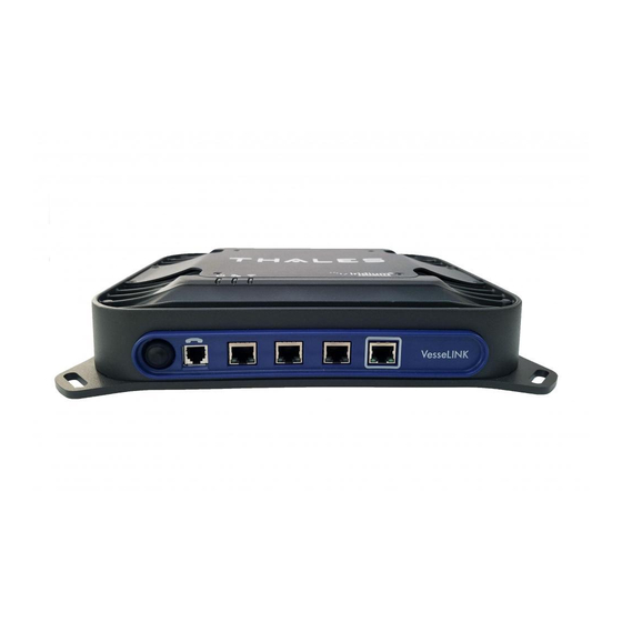
The BDU front panel (left to right) has a main power button, one RJ-14 jack for POTS (Plain Old Telephone Service) Phone(s), three PoE (Power over Ethernet) RJ-45 connections for VoIP phones or Ethernet-based devices, and one WAN (Wide Area Network) connection primarily used to connect an external cellular modem or VSAT. -
Page 15: Above Deck Unit (Adu) / Antenna
Above Deck Unit (ADU) / Antenna The Above Deck Unit (ADU) or Antenna is a standalone unit that connects to the BDU through a single coaxial cable. DC power, RF transmit and receive signals, control data and GPS data are communicated between the ADU and BDU using this single coaxial cable. -
Page 16: Vesselink ™ Kit Components
Hardware 1100791-501 Kit, Antenna Maritime Mounting Hardware 1600901-1 Above Deck Unit / Antenna Unit ™ 3402131-1 Quick Start Guide (QSG) VesseLINK 3900011-1 Mounting Template, Terminal Unit 3900014-1 Mounting Template, Antenna ™ 4102947-501 Terminal Unit VesseLINK ... -
Page 17: Tools And Supplies Needed For Installation
™ Table 1-3 Available VesseLINK Accessories Description Part Number 19” Rack Mount Shelf Kit 1100796-501 Thales SureLINK IP Handset Kit 1100818-501 Power Supply, AC/DC 12V – 160W 84670-001 Cable AC Power with USA Plug Type B IEC 60320- 854024-001 C13 6 ft... - Page 18 THIS PAGE INTENTIONALLY LEFT BLANK Installation Guide 84464 Rev. B...
-
Page 19: Installation
3. Conduct an inventory of all components and parts using the equipment packing list provided with the equipment. Any missing items and/or shipping damage should be reported immediately to Thales Customer Service Department (Tel: (800) 324-6089 or email customer.service@thalesdsi.com). Precautions During Installation The following steps should be followed to prevent damage to the equipment: 1. -
Page 20: Installation
Included in each kit are mounting templates if custom mounting hardware is necessary for your application. ™ It is important to note that the coaxial cable provided in the VesseLINK kit, or the Thales ™... -
Page 21: Figure 2-1 Placinga
• Ground the antenna using a heavy ground cable (not included) from the ground terminal on the bottom of the antenna to the vessel’s ground to protect the system from unwanted surges and voltage differentials. • Use the supplied RF cable designed for VesseLINK ™ . Do not alter the provided cable prior to installation. -
Page 22: Figure 2-2 Recommended
Distance d = 2.0m for S-Band up to 50kW d = 4.0m for X & C-Bands up to 50kW Figure 2-2 Recommended Antenna Placement with Existing Radar Installation Guide 84464 Rev. B... -
Page 23: Installation Of Adu / Antenna
The Antenna Mounting Template is provided in Appendix A for use in fabricating a custom plate. A mounting plate is not included in the kit, but Thales offers two pole mount brackets as NOTE accessory items. (Refer to Appendix C.) The antenna is mounted with either four M6 (torque to 6 N*m (4.4 ft-lbs.)) or four M10 (torque... - Page 24 Installation of ADU / Antenna using M6 Hardware 1. Use the template information provided in Appendix A to create the appropriate hole pattern in the desired mounting surface for the chosen mounting hardware. Hole sizing and provided hardware are shown for through hole mounting as shown in Appendix A.
-
Page 25: Figure 2-4 Above Decku
Figure 2-4 Above Deck Unit / Antenna Installation (M6 Hardware) Table 2-1 Installation Kit, Mounting Hardware (M6 Hardware) Item Part Number Description Number Screw, Button HD Socket Cap M6x1x20mm A4-70 SS 82771-001 Washer, Split M6 (DIN 127B) A4 L/W SS 71300-001 Washer, Flat M6 A4-80 (DIN 125 ISO 7089) SS 71299-001... - Page 26 Installation of ADU / Antenna using M10 Hardware 1. Use the template information provided in Appendix A to create the appropriate hole pattern in the desired mounting surface for the chosen mounting hardware. Hole sizing and provided hardware are shown for through hole mounting as shown in Appendix A.
-
Page 27: Figure 2-5 Above Decku
Figure 2-5 Above Deck Unit / Antenna Installation (M10 Hardware) Table 2-2 Installation Kit, Mounting Hardware (M10 Hardware) Item Part Number Description Number Screw, Button HD Socket Cap M10x1.5x25mm A4-70 (ISO 82770-001 7380) SS Screw, Button HD Socket Cap M10x1.5x30mm A4-70 (ISO 82770-002 7380) SS Washer, Split M10 MED L/W A4 (DIN 127B) SS... -
Page 28: Installing The Below Deck Unit
Installing The Below Deck Unit ™ The VesseLINK Below Deck Unit is designed for ease of installation with four corner mounting locations for direct mounting. It is recommended that the BDU be mounted in a cool dry place leaving sufficient room (3 in. or 8 cm) between the BDU and other equipment to allow for proper airflow. -
Page 29: Sim Card With
BDU can be mounted in any orientation but for best performance, it is recommended that it is mounted horizontally with the Thales logo facing up. This will give the best NOTE protection against any spills or dripping water and allows for the best heat transfer. -
Page 30: Figure 2-8 Installing Sim C
Figure 2-8 Installing SIM Card and Engaging the Lock d. Secure the SIM Card cover once the SIM Card has been locked into place to prevent moisture or dust intrusion. (Figure 2-9) Figure 2-9 Secure the SIM Card Cover 5. Connect the provided RF cable that goes to the antenna. The BDU should be grounded. -
Page 31: Connecting Power To The Bdu
Connecting Power To The BDU The BDU has 2 connections for direct power depending on the vessel power available: • AC Operation: Supplied external AC/DC supply with power cord. (Refer to Figure 2-10) Figure 2-10 AC/DC Power Supply To safely disconnect the BDU from the power source, unplug the unit from the power outlet. -
Page 32: Dc Power Connection
DC Power Connection Installations using the DC power cable (PN 855024-020) should use the red and black primary power wires as well as the yellow remote wire as the ON/OFF switching source. The BDU will turn OFF with the vehicle’s ignition switch when the yellow remote line is connected, so it is important to make that connection in the vehicle (see Figure 2-11). -
Page 33: Figure 2-12 24V Dc Power
Figure 2-12 24V DC Power Connection 3. Connect the YELLOW wire to the ignition (or similar) via the fuse box or panel. 2-15 Installation Guide 84464 Rev. B... -
Page 34: System Status Indicators
System Status Indicators Now that the system installation is complete, press the start button on the BDU. In Figure 2-13, from Left to Right these are: System (Overall System Status), Satellite (Satellite Connection Status) and Wi-Fi (Wireless Network Status). Figure 2-13 Below Deck Unit (BDU) LEDs Table 2-4 Below Deck Unit (BDU) LED Status Indicator Description... - Page 35 The Indicator Colors are: Solid Green: Operational Flashing Green: start-up or in progress of configuring or acquiring NOTE service. Solid Red: fault requires user attention (Open Management Portal Alerts) Flashing Red: critical fault requiring immediate attention. For additional information, refer to Chapter 3 Troubleshooting 2-17 Installation Guide 84464 Rev.
- Page 36 THIS PAGE INTENTIONALLY LEFT BLANK 2-18 Installation Guide 84464 Rev. B...
-
Page 37: Troubleshooting
TROUBLESHOOTING TROUBLESHOOTING Table 3-1 Troubleshooting PROBLEM SOLUTION • Flashing GREEN light indicates that it is acquiring the satellite. If it continues to flash for more than 5 minutes, check that the Satellite LED Flashing antenna has a clear view of the sky. GREEN •... - Page 38 PROBLEM SOLUTION • Ensure Terminal Unit is powered ON • Ensure Wi-Fi is enabled and connected to ThalesLINK (or renamed SSID). If using a Wi-Fi enabled device, the Wi-Fi LED on the BDU should be solid GREEN. If not using Wi-Fi, ensure Cat 5 cable is connected to one of the three Ethernet ports (NOT WAN or POTS Port).
- Page 39 PROBLEM SOLUTION • Check signal bars at the top of the Management Portal. If no bars are highlighted, the satellite is not being detected. Wait a few minutes to see if the signal strength improves as another satellite comes into view. •...
- Page 40 PROBLEM SOLUTION • Check LED status on BDU or on Management Portal. Make sure there are no RED LEDs. Check for Alerts in Management Portal by selecting the Alerts menu item • Reboot the system and recheck for any Alerts that have been generated.
-
Page 41: Technical Specifications
Type Electronically steered phased array Polarization RHCP Gain 9.5 dBi Beam Width 31° typical per beam ™ VesseLINK coverage provides useful link margin up to roll = 20° Power Main Power AC Input Voltage 100-240 VAC (AC Brick) Frequency 50/60 Hz... - Page 42 Environmental Operating Temp -30°C to +55°C IP Rating IP67 Operating Temp -30°C to +55°C IP Rating IP31 Mechanical Diameter 14.5" (36.8cm) Height 7.5" (19.8cm) Weight 7 lbs (3.2kg) Length 12 inches (30cm) Width 9 inches (23cm) Height 3 Inches ( 7.6cm) Weight 7.5 lbs (3.4kg) AC Power...
-
Page 43: Connector Details
Connector Details: General Purpose Inputs / Outputs (GPIO) The DB-15 connector with Pin out shown in Figure 4-1. Figure 4-1 GPIO Connector Pin Detail Table 4-2 GPIO Connector Pin Definition Pin No Name Description GND1 Ground Audio_In + Radio Gateway functionality, differential (+) Hi-Z Audio Input from external Radio Audio_Out + Radio Gateway functionality, Differential (+) Low-Z Audio Output... -
Page 44: Bdu 12V Connection Detail
BDU 12V Connection Detail Type: KPPX-4x connector (or similar) shown in Figure 4-2. PIN NO OUTPUT 2, 4 1, 3 VIEW INTO END OF MATING CONNECTOR Figure 4-2 12V Input and Mating Connector Detail BDU 10-32VDC Connection Detail Type: 684M7W2103L201 connector (or similar) shown in Figure 4-3. A1 = V+ /10-32VDC A2 =V- /GND Pin 5 = Ignition... -
Page 45: Acronyms / Glossary
ACRONYMS / GLOSSARY Acronyms / Glossary Table 5-1 List of Acronyms Acronym Description Above Deck Unit Antenna Application Programming Interface Broadband Active Antenna Broadband Application Electronics Broadband Core Transceiver Below Deck Unit Terminal Unit Built In Test DTMF Dual Tone Multi-Frequency Enhanced Broadband ETSI European Telecommunications Standards Institute... -
Page 46: Table 5-2 List Of Definitions
Acronym Description Satellite Vehicle Transmission Control Protocol Terminal Unit User Datagram Protocol UL/DL Uplink/Downlink VLAN Virtual Local Area Network VOIP Voice of Internet Protocol Wide Area Network WI-FI Wireless Network WPA2-PSK Wi-Fi Protected Access 2 – Pre-Shared Key Table 5-2 List of Definitions Acronym Description Application Programming... - Page 47 Acronym Description Low Gain Antenna External antenna that connects to the BDU via a coaxial cable. The LGA1 and LGA2 support the future Certus Certus 100 and 200 capabilities Management Management Portal: A web page served from the Portal Terminal Unit that brings together the diverse status and configuration information of the LMC 350 in one place.
- Page 48 THIS PAGE INTENTIONALLY LEFT BLANK Installation Guide 84464 Rev. B...
-
Page 49: Index
List of Tools and Supplies Needed ..................1-7 Mounting the Above Deck Unit / Antenna ................2-2 System Status Indicators ......................2-16 Introduction ..........................1-1 Kit Components ™ VesseLINK ..........................1-6 Maintenance Troubleshooting ........................3-1 Index-1 Installation Guide 84464 Rev. B... - Page 50 System Overview Above Deck Antenna Unit ....................... 1-5 Below Deck Unit (BDU) ......................1-2 Technical Specifications ......................4-1 Index-2 Installation Guide 84464 Rev. B...
-
Page 51: Appendixa Antenna Mounting Plate Template (Pn 3900014-1
Appendix A Antenna Mounting Plate Template (PN 3900014-1) Installation Guide 84464 Rev. B... -
Page 53: Appendixb Bdu Mounting Plate Template (Pn 3900011-1
Appendix B BDU Mounting Plate Template (PN 3900011-1) Installation Guide 84464 Rev. B... -
Page 55: Appendixc Antenna Pole Mounting (Optional
The bracket is designed to work on standard 1.9-inch (with included bushing), 52mm and 3-inch poles (poles not included). This bracket has mounting holes that match the mounting points on the bottom of the antenna (M6 or M10). Figure C-1 Thales Antenna Mounting Bracket (Shown With Poles, Not Included) Installation Guide 84464 Rev. B... -
Page 56: Figure C-2 Thales Antenna
Antenna Pole Mount using M6 Hardware Shown Assembled Exploded View Figure C-2 Thales Antenna Pole Mount Kit – M6 (PN 85736-001) Table C-1 Antenna Pole Mount using M6 Hardware Kit (PN 85736-001) Item Description Comment Number Outside Diameter 1.9” OD... -
Page 57: Figure C-3 Thales Antenna
Shown Assembled Exploded View Figure C-3 Thales Antenna Pole Mount Kit – M10 (PN 85739-001) Table C-2 Antenna Pole Mount using M10 Hardware Kit (PN 85739-001) Item Description Comment Number Outside Diameter 1.9” OD Blue Loctite Apply to item 8, 9 , 12 S.S. - Page 58 Thales Defense & Security, Inc. 22605 Gateway Center Drive | Clarksburg MD 20871 Toll-Free 1.800.324.6089 | Phone: 240.864.7000 | Fax: 240.864.7920 Email: Customer.Service@thalesdsi.com | Website: www.thalesdsi.com...
Need help?
Do you have a question about the VesseLINK and is the answer not in the manual?
Questions and answers