
Subscribe to Our Youtube Channel
Related Manuals for wtw Multi 3430


Summary of Contents for wtw Multi 3430
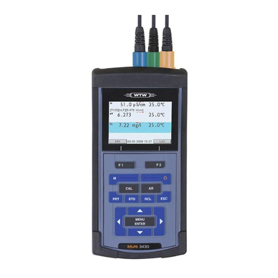
- Page 1 Operating manual Multi 3430 Digital pH / dissolved oxygen / conductivity meter for 3 digital IDS sensors ba75865e02 12/2009...
- Page 2 © Copyright Weilheim 2009, WTW GmbH Reproduction in whole - or even in part - is prohibited without the express writ- ten permission of WTW GmbH, Weilheim. Printed in Germany. ba75865e02 12/2009...
-
Page 3: Table Of Contents
Contents Multi 3430 - Contents Overview ........7 Keypad . - Page 4 Contents Multi 3430 4.6.3 Settings for pH measurements ....39 4.6.4 pH calibration ......41 4.6.5...
- Page 5 Multi 3430 Contents pH ......... . 90 Conductivity.
- Page 6 Contents Multi 3430 ba75865e01 12/2009...
-
Page 7: Overview
(D.O.) measurements quickly and reliably. The Multi 3430 provides the maximum degree of operating comfort, reliability and measuring certainty for all applications. The Multi 3430 supports you in your work with the following functions: proven calibration procedures automatic stability control (AR),... -
Page 8: Keypad
Overview Multi 3430 The two USB interfaces (USB-A and USB-B) enable you to: Transmit data to – a USB memory device – a PC Update the meter firmware. Keypad MENU MENU ENTER ENTER pH 3430 In this operating manual, keys are indicated by brackets <..> . -
Page 9: Display
Multi 3430 Overview <STO>: Saves a measured value manually <STO >: Opens the menu for the automatic save function <RCL>: Displays the manually stored measured values <RCL >: Displays the automatically stored measured values < >< >: Menu control, navigation <... - Page 10 Overview Multi 3430 Function display AutoCal Calibration with automatic buffer recognition, e.g. indicators e.g. TEC with the buffer set: Technical buffers ConCal Calibration with any buffers Error An error occurred during calibration Stability control (AutoRead) is active HOLD Measured value is frozen (<AR> key)
-
Page 11: Socket Field
USB B (Device) interface Service interface CAUTION Only connect sensors to the meter that cannot return any voltages or currents that are not allowed (> SELV and > current circuit with current limiting). WTW IDS sensors meet these requirements. ba75865e02 12/2009... -
Page 12: Automatic Sensor Recognition
To be able to use the automatic sensor recognition, a meter that sup- ports the automatic sensor recognition (e.g. Multi 3430) and a digital IDS sensor are required. In digital IDS sensors, sensor data are stored that clearly identify the sensor. - Page 13 Multi 3430 Overview Sensor data from IDS IDS sensors transmit the following sensor data to the meter: sensors SENSOR ID – Sensor name – Sensor series number Calibration data – Calibration date – Calibration characteristics – Calibration interval – Selected buffer set (IDS pH sensors only) –...
- Page 14 Overview Multi 3430 ba75865e02 12/2009...
-
Page 15: Safety
Multi 3430 Safety Safety This operating manual contains basic instructions that you must follow during the commissioning, operation and maintenance of the meter. Consequently, all responsible personnel must read this operating man- ual before working with the meter. The operating manual must always be available within the vicinity of the meter. -
Page 16: Authorized Use
Safety Multi 3430 Authorized use The authorized use of the meter consists exclusively of the measure- ment of the pH, ORP, conductivity and dissolved oxygen in a field and laboratory environment. The technical specifications as given in chapter 7 T... - Page 17 Safety datasheets of the chemical manufacturers. CAUTION In addition to the safety instructions mentioned here, also follow the safety instructions of the sensors used. The operating manuals of the sensors are available on the sup- plied CD and on the Internet under www.WTW.com. ba75865e02 12/2009...
- Page 18 Safety Multi 3430 ba75865e02 12/2009...
-
Page 19: Commissioning
Detailed operating manual (4 languages) CD-ROM Power supply The Multi 3430 is supplied with power in the following ways: Battery operation with NiMh rechargeable batteries Mains operation with the supplied power pack. The NiMh rechargeable batteries are automatically charged while the power pack is connected. -
Page 20: Connecting The Power Pack / Charging The Batteries
Commissioning Multi 3430 Place four rechargeable batteries (type Mignon AA) in the bat- tery compartment. CAUTION Make sure that the poles of the rechargeable batteries are posi- tioned correctly. ± ± signs on the batteries must correspond to the signs in the battery compartment. -
Page 21: Switching On The Meter
Multi 3430. Connect the original power pack to an easily accessible power outlet. The batteries are automatically charged in the background. You can continue to work with the Multi 3430 during the charg- ing process. The symbol is displayed. Note Charge the batteries completely prior to putting the meter into operation for the first time. - Page 22 Commissioning Multi 3430 ba75865e02 12/2009...
-
Page 23: Operation
Multi 3430 Operation Operation Switching on the meter Switching on Press the <On/Off> key. The meter performs a self-test. The display shows the manufacturer's logo while the self-test is being performed. If a sensor is connected the measured value display appears. -
Page 24: General Operating Principles
An overview of the operating elements and the display is given in sec- display tion 1.1 and section 1.2. Operating modes, An overview of the operating modes and navigation of the Multi 3430 is navigation given in section 4.2.1 and section 4.2.3. 4.2.1 Operating modes... -
Page 25: Display Of Several Sensors In The Measuring Mode
Multi 3430 Operation 4.2.2 Display of several sensors in the measuring mode The measured values of the connected sensors can be displayed in the following ways: Clear display of all connected sensors Detailed display of one sensor (e.g. incl. CMC feature with pH sensors) With the softkey you can very easily switch between the two display types. -
Page 26: Navigation
Operation Multi 3430 4.2.3 Navigation Measured value display In the measured value display, you can use < >< > to select one of several connected sensors. The selected sensor is displayed with a colored background. The following actions / menus refer to the selected sensor open the menu for calibration and measurement settings with <MENU/ENTER>... - Page 27 Multi 3430 Operation General Language: Deutsch Beep: Volume Illumination: Brightness: Switchoff time: Temperature unit °C Calibration data storage 22.09.2009 08:00 Functions Functions are designated by the name of the function. They are immediately carried out by confirming with <MENU/ENTER>. Exam- ple: Display the Calibration record function.
-
Page 28: Example 1 On Navigation: Setting The Language
Operation Multi 3430 4.2.4 Example 1 on navigation: Setting the language Press the <On/Off> key. The measured value display appears. The instrument is in the measuring mode. Info 30.09.2009 08:00 Open the Storage & config menu with <MENU/ENTER >. The instrument is in the setting mode. - Page 29 Multi 3430 Operation System General Interface Clock function Service information Reset 22.09.2009 08:00 Select the General submenu with < >< >. The current selection is displayed with a frame. Open the General submenu with <MENU/ENTER>. General Language: Deutsch Beep: Illumination:...
-
Page 30: Example 2 On Navigation: Setting The Date And Time
Operation Multi 3430 Select the required language with < >< >. Confirm the setting with <MENU/ENTER>. The meter switches to the measuring mode. The selected language is active. 4.2.5 Example 2 on navigation: Setting the date and time The measuring instrument has a clock with a date function. The date and time are indicated in the status line of the measured value display. - Page 31 Multi 3430 Operation Clock function Date format: dd.mm.yy Date: 30.09.2009 Time: 14:53:40 22.09.2009 08:00 Select and confirm the Time menu with < >< > and <MENU/ ENTER>. The hours are highlighted. Change and confirm the setting with < >< > and <MENU/ ENTER>.
-
Page 32: Sensor-Independent Settings
Operation Multi 3430 Sensor-independent settings The Storage & config menu includes the following settings: System (see section 4.3.1). Data storage (see section 4.3.2) 4.3.1 System Overview The following sensor-independent meter characteristics can be adjusted in the Storage & config/System menu:... - Page 33 Multi 3430 Operation Menu item Setting Description System / General / Temperature °C Temperature unit, unit °F degrees Celsius or degrees Fahrenheit. All temperatures are displayed with the selected unit. System / General / Stability control Switches on or off the auto-...
-
Page 34: Data Storage
This menu contains all functions to display, edit and erase stored mea- sured values. Note Detailed information on the storage functions of the Multi 3430 is given in section 4.9. 4.3.3 Automatic Stability control The automatic Stability control (AutoRead) function continuously checks the stability of the measurement signal. -
Page 35: Channel Display
Unit for slope mV/pH QSC: 30.09.2009 08:00 Channel display The Multi 3430 manages the connected sensors and displays which sensor is plugged to which connection. Channel display Display of the plug position for the respective parameter The red bar indicates for... -
Page 36: Ph Value
This facilitates interference-free measurements also in the following cases: Measurement in grounded test samples Measurement with several sensors connected to one Multi 3430 in one test sample Temperature For reproducible pH measurements, it is essential to measure the tem- measurement perature of the test sample. -
Page 37: Measuring The Ph Value
Multi 3430 Operation 4.6.2 Measuring the pH value Perform the preparatory activities according to section 4.6.1. Immerse the IDS pH sensor in the test sample. Info 30.09.2009 08:00 Select the pH or mV display with <M>. Stability control The stability control function (AutoRead) continually checks the stability (AutoRead ) of the measurement signal. - Page 38 Operation Multi 3430 Note You can prematurely terminate the Stability control function manually with <MENU/ENTER> at any time. If the Stability control function is pre- maturely terminated, the current measurement data are output to the interface without the AutoRead info.
-
Page 39: Settings For Ph Measurements
Multi 3430 Operation 4.6.3 Settings for pH measurements Overview The following settings are possible for pH measurements: Resolution Calibration interval Buffers for calibration Automatic stability control Unit for slope Calibration record (display) Settings The settings are made in the menu for calibration and measurement settings of the pH/ORP measurement. - Page 40 Operation Multi 3430 Menu item Possible set- Description ting pH resolution 0.001 Resolution of the pH display 0.01 mV resolution Resolution of the mV dis- play Reset Resets all sensor settings to the delivery condition (see section 4.11.1). QSC /First calibra-...
-
Page 41: Ph Calibration
Multi 3430 Operation 4.6.4 pH calibration Why calibrate? IDS pH sensors age. This changes the zero point (asymmetry) and slope of the IDS pH sensor. As a result, an inexact measured value is displayed. Calibration determines the current values of the zero point and slope of the IDS pH sensor and stores them in the measuring instrument. - Page 42 Operation Multi 3430 Buffer set * pH val- Merck 5 * 4.010 25 °C 7.000 10.000 DIN 19267 1.090 25 °C 4.650 6.790 9.230 Mettler Toledo US * 1.679 25 °C 4.003 7.002 10.013 Mettler Toledo EU * 1.995 25 °C 4.005...
- Page 43 Multi 3430 Operation Buffer set * pH val- Merck 5 * 4.010 25 °C 7.000 10.000 DIN 19267 1.090 25 °C 4.650 6.790 9.230 Mettler Toledo US * 1.679 25 °C 4.003 7.002 10.013 Mettler Toledo EU * 1.995 25 °C 4.005...
- Page 44 Operation Multi 3430 Buffer set * pH val- Precisa * 3.996 25 °C 7.003 8.999 Reagecon TEC * 2.000 25 °C 4.010 7.000 10.000 Reagecon 20 * 2.000 20°C 4.000 7.000 10.000 13.000 Reagecon 25 * 2.000 25 °C 4.000 7.000...
- Page 45 Multi 3430 Operation Calibration points Calibration can be performed using one to five buffer solutions in any order (single-point to five-point calibration). The meter determines the following values and calculates the calibration line as follows: Determined val- Displayed calibration data...
- Page 46 Operation Multi 3430 Sample record 31.07.2009 15:55 Multi 3430 Ser. no. B211371282 CALIBRATIONpH 31.07.2009 16:13:33 SenTix 940 Ser. no. B211371282 AutoCal TEC Buffer 1 4.01 Buffer 2 7.00 Buffer 3 10.01 Voltage 1 184.0 mV 24.0 °C Voltage 2 3.0 mV 24.0 °C...
-
Page 47: Calibration Interval
Multi 3430 Operation Preparatory activities Perform the following preparatory activities when you want to calibrate: Connect the IDS pH sensor to the meter. The pH measuring window is displayed. Keep the buffer solutions ready. 4.6.5 Calibration interval The calibration evaluation is displayed as a sensor symbol. -
Page 48: Carrying Out An Automatic Calibration (Autocal)
Operation Multi 3430 4.6.6 Carrying out an automatic calibration (AutoCal) Make sure that in the sensor menu, Buffer menu, the buffer set is cor- rectly selected (see page 39). Use any one to five buffer solutions of the selected buffer set in ascend- ing or descending order. - Page 49 Multi 3430 Operation 30.09.2009 08:00 Wait for the end of the measurement with stability control or accept the calibration value with <MENU/ENTER>. The calibration display for the next buffer appears. 30.09.2009 08:00 If necessary, finish the calibration procedure as a single-point calibration with <M>.
- Page 50 Operation Multi 3430 30.09.2009 08:00 Wait for the measurement with stability control to be completed or terminate the stability control and take over the calibration value with <MENU/ENTER>. The calibration display for the next buffer appears. 30.09.2009 08:00 Finish the calibration procedure as a two-point calibration with <M>.
- Page 51 Multi 3430 Operation 30.09.2009 08:00 Use <M> to finish the calibration. The calibration record is displayed. Switch to calibration with the next buffer with <MENU/ ENTER>. Note Calibration is automatically completed after the last buffer of a buffer set has been measured. Then the calibration record is displayed.
-
Page 52: Carrying Out A Manual Calibration (Concal)
Operation Multi 3430 4.6.7 Carrying out a manual calibration (ConCal) Single-point calibration Use any buffer solution for this rapid method. The calibration will be the more exact the nearer the pH value of the buffer solution is to that of the test sample. - Page 53 Multi 3430 Operation 30.09.2009 08:00 Wait for the measurement with stability control to be com- pleted. Set the nominal buffer value for the measured temperature with < >< >. Take over the calibration value for the asymmetry with <MENU/ ENTER>.
-
Page 54: Displaying Calibration Records
Operation Multi 3430 Continuing with two- Thoroughly rinse the IDS pH sensor with distilled water. point calibration Immerse the IDS pH sensor in buffer solution 2. Start the measurement with <MENU/ENTER>. The measured value is checked for stability (stability control). - Page 55 Multi 3430 Operation Menu item Setting/func- Description tion Calibration / Displays the calibration Calibration data stor- records. Further options: Scroll through the cali- bration records with < >< >. Output the displayed calibration record to the interface with <PRT>. Output all calibration records to the interface with <PRT...
-
Page 56: Continuous Measurement Control
Operation Multi 3430 4.6.9 Continuous measurement control (CMC function) The Continuous Measurement Control (CMC function) facilitates to evaluate the current measured value instantly and definitely. After each successful calibration the scale of the pH measuring range is displayed in the measured value display. Here you can very clearly see whether or not the current measured value is in the calibrated part of the measuring range. -
Page 57: Qsc Function (Sensor Quality Control)
Multi 3430 Operation 4.6.10 QSC function (sensor quality control) General information The QSC function (Quality Sensor Control) is a new sensor evaluation on the QSC function for digital IDS sensors. It evaluates the condition of an IDS pH sensor individually and with a very fine grading. - Page 58 Operation Multi 3430 QSC calibration The QSC function is enabled by once carrying out an additional three- point calibration with special QSC buffer solutions. It covers the entire measuring range of the sensor. The QSC initial calibration determines the actual condition of the sensor and stores it as a reference in the sensor.
- Page 59 Multi 3430 Operation As soon as the three-point calibration has been successfully carried out you can decide whether to accept or discard the cal- ibration as the QSC initial calibration. The QSC initial calibration is completed. The sensor is calibrated. If you want to calibrate with special buffers for your measurements, you can subsequently carry out a normal calibration with your buffers.
-
Page 60: Orp Voltage
This facilitates interference-free measurements also in the following cases: Measurement in grounded test samples Measurement with several sensors connected to one Multi 3430 in one test sample Preparatory activities Perform the following preparatory activities when you want to measure: Connect the IDS ORP sensor to the meter. - Page 61 Multi 3430 Operation Select the mV display with <M>. Stability control The stability control function (AutoRead) continually checks the stability (AutoRead ) of the measurement signal. The stability has a considerable impact on the reproducibility of measured values. The display of the measured parameter flashes until a stable measured value is available.
-
Page 62: Settings For Orp Measurements
Operation Multi 3430 4.7.3 Settings for ORP measurements Overview The following settings are possible for ORP measurements: Resolution Automatic stability control Settings The settings are made in the menu for measuring settings of the ORP measurement. To open the settings, display the required measured parameter in the measured value display and press the <MENU/... -
Page 63: Conductivity
Multi 3430 Operation Conductivity 4.8.1 General information You can measure the following variables: Conductivity Specific resistance Salinity Total dissolved solids (TDS) Temperature IDS sensors measure the temperature with a temperature sensor inte- measurement grated in the IDS sensor. Preparatory activities Perform the following preparatory activities when you want to measure: Connect an IDS conductivity sensor to the meter. - Page 64 Operation Multi 3430 Selecting the You can switch between the following displays with <M>: displayed Conductivity [μS/cm] / [mS/cm] measured parameter Resistivity [Ω·cm] / [kΩ·cm] / [MΩ·cm] Salinity SaL [ ] Total dissolved solids TDS [mg/l] / [g/l] The factor to calculate the total dissolved solids is set to 1.00 in the fac- tory.
- Page 65 Multi 3430 Operation Using <MENU/ENTER>, activate the Stability control function manually. The [AR] status indicator appears while the measured value is assessed as not stable. A progress bar is displayed and the display of the measured parameter flashes. The [HOLD][AR] status indicator appears as soon as a stable measured value is recognized.
-
Page 66: Temperature Compensation
Operation Multi 3430 4.8.3 Temperature compensation The calculation of the temperature compensation is based on the pre- set reference temperature, 20 °C or 25 °C. It appears on the display as Tr20 or Tr25. You can select one of the following temperature compensation meth-... -
Page 67: Settings For Ids Conductivity Sensors
Multi 3430 Operation 4.8.4 Settings for IDS conductivity sensors Overview The following settings are possible for IDS conductivity sensors: Calibration record (display) Calibration interval Reference temperature Temperature compensation TDS factor Unit of the temperature Automatic Stability control Settings The settings are made in the Measurement menu for the measured parameter, conductivity. - Page 68 Operation Multi 3430 Menu item Possible Description setting Measurement / 0.450 ... Display and setting option of the Measuring cell / 0.475 ... cell constant of any measuring Man. cell const. 0.500 cm cells (man). Measurement / Procedure for temperature com- Temp.
- Page 69 Multi 3430 Operation Setting menu of Menu item Possible set- Description LR325/01 ting Measurement / 0.090 ..Display and setting option of Measuring cell / 0.100 ... the cell constant of any mea- Cell constant 0.110 cm suring cells (man).
-
Page 70: Determining The Cell Constant (Calibration In Control Standard)
Operation Multi 3430 4.8.5 Determining the cell constant (calibration in control standard) Why determine the cell Aging slightly changes the cell constant, e. g. due to coatings. As a constant? result, an inexact measured value is displayed. The original character- istics of the cell can often be restored by cleaning the cell. - Page 71 Multi 3430 Operation Display Calibration Cell constant [cm record Within the range 0.450 ... 0.500 cm Outside the range Error Error 0.450 ... 0.500 cm Eliminate the error according to chapter 6 W HAT TO DO IF Determining the cell...
-
Page 72: Displaying Calibration Records
Operation Multi 3430 Wait for the end of the measurement with stability control or accept the calibration value with <MENU/ENTER>. The calibration record is displayed and output to the interface. Switch to the measured value display with <MENU/ENTER>. 4.8.6 Displaying calibration records The calibration data can be displayed and then output to the interface. -
Page 73: Data Storage
- 4 levels (+++, ++, +, -, or no evaluation) or - QSC (percentage) Storage locations The Multi 3430 meter has two measurement data memories. The mea- sured values recorded either manually or automatic are stored sepa- rately in individual measurement data memories. -
Page 74: Manual Storage
Operation Multi 3430 4.9.1 Manual storage You can transmit a measurement dataset to the data storage as fol- lows. The dataset is at the same time output to the interface: Press the <STO> key shortly. The menu for manual storage appears. -
Page 75: Automatic Storage At Intervals
Multi 3430 Operation 4.9.2 Automatic storage at intervals The storage interval (Interval) determines the time interval between automatic storage processes. Each storage process transmits the cur- rent dataset to the interface at the same time. Configuring the Press the <STO >... - Page 76 Operation Multi 3430 Starting the automatic To start the automatic storage function, select Continue with < >< > storage function and confirm with <MENU/ENTER>. The meter switches to the mea- sured value display. Remaining storage duration Graphical display of the...
-
Page 77: Editing The Measurement Data Storage
Multi 3430 Operation 4.9.3 Editing the measurement data storage The contents of the manual or automatic measurement data storage can be shown on the display. Each of the measurement data storages has a function to erase the entire contents. Editing the data storage The storage is edited in the menu, Storage &... - Page 78 Operation Multi 3430 Menu item Setting/func- Description tion Data storage / Erases the entire manual Manual data storage / measurement data stor- Erase age. Note: All calibration data remains stored when this action is performed. Display presentation Manual data storage (200) 3 of 64 of a dataset 30.09.2009 11:24:16 ID number: 1...
-
Page 79: Erasing The Measurement Data Storage
Multi 3430 Operation <ESC>. 4.9.4 Erasing the measurement data storage How to erase the measurement data memory is described in section 4.9.3 E DITING THE MEASUREMENT DATA STORAGE ba75865e02 12/2009... -
Page 80: Transmitting Data (Usb Interfaces)
Via the USB-A interface (USB Host) it is possible to transfer data to an external USB memory device. 4.10.3 Connecting the PC / USB-B interface (USB Device) Connect the Multi 3430 to the PC via the USB-B interface. Installation of the USB System requirements of the PC for installation of the USB driver:... -
Page 81: Connecting The Usb Memory Device / Usb-A Interface (Usb Host)
– Stop bits: 1 4.10.4 Connecting the USB memory device / USB-A interface (USB Host) Connect the USB-A interface (USB Host) of the Multi 3430 to a USB flash drive. Connect the USB printer or a USB memory device to the USB Host interface. -
Page 82: Options For Data Transmission
Operation Multi 3430 4.10.5 Options for data transmission Via the USB-B interface you can transmit data to a PC. Via the USB-A interface you can transmit data to a USB memory device. The following table shows which data are transmitted to the interface in which way:... -
Page 83: Reset
Multi 3430 Operation 4.11 Reset You can reset (initialize) all sensor settings and sensor-independent settings separately from each other. 4.11.1 Resetting the measurement settings Note The calibration data are reset to the default settings together with the measuring parameters. Recalibrate after performing a reset. - Page 84 Operation Multi 3430 The following settings for ORP measurements are reset to the default settings with the Reset function: Setting Default settings Resolution mV Man. temperature 25 °C Stability control The sensor settings are reset under the Reset menu item in the menu for calibration and measurement settings.
-
Page 85: Resetting The System Settings
Multi 3430 Operation 4.11.2 Resetting the system settings The following system settings can be reset to the default condition: Setting Default settings Language English Acoustic signal Volume Baud rate 4800 Baud Output format ASCII Decimal separator Brightness Illumination Auto Switchoff time Temperature unit °C... - Page 86 Operation Multi 3430 ba75865e02 12/2009...
-
Page 87: Maintenance, Cleaning, Disposal
Multi 3430 Maintenance, cleaning, disposal Maintenance, cleaning, disposal Maintenance The only maintenance activity required is replacing the batteries. Note See the relevant operating manuals of the IDS sensors for instructions on maintenance. 5.1.1 Replacing the rechargeable batteries Unscrew the two screws (1) on the underside of the meter. -
Page 88: Cleaning
Maintenance, cleaning, disposal Multi 3430 Close the battery compartment (2) and tighten the screws (1). Cleaning Occasionally wipe the outside of the measuring instrument with a damp, lint-free cloth. Disinfect the housing with isopropanol as required. CAUTION The housing is made of synthetic material (ABS). Thus, avoid con- tact with acetone or similar detergents that contain solvents. -
Page 89: What To Do If
Multi 3430 What to do if... What to do if... General information Sensor symbol flashes Cause Remedy – Calibration interval expired – Recalibrate the measuring system Cause Remedy – Batteries almost empty – Charge the batteries (see section 3.3.2 C... - Page 90 What to do if... Multi 3430 Error message OFL, UFL Cause Remedy IDS pH sensor: – Measured value outside the – Use suitable IDS pH sensor measuring range – Air bubble in front of the dia- – Remove air bubble phragm –...
- Page 91 Multi 3430 What to do if... No stable measured Cause Remedy value IDS pH sensor: – Junction contaminated – Clean the junction – Membrane contaminated – Clean membrane Test sample: – pH value not stable – Measure with air excluded if necessary –...
-
Page 92: Conductivity
What to do if... Multi 3430 Conductivity Error message, Cause Remedy – Measured value outside the – Use suitable IDS conductiv- measuring range ity sensor Error message, Cause Remedy Error – IDS conductivity sensor contam- – Clean and if necessary,... -
Page 93: Technical Data
Multi 3430 Technical data Technical data General data Dimensions Approx. 180 x 80 x 55 mm Weight Approx. 0.4 kg Mechanical structure Type of protection IP 67 Electrical safety Protective class Test certificates Ambient Storage - 25 °C ... + 65 °C... -
Page 94: Measuring Ranges, Resolution, Accuracy
Technical data Multi 3430 Applicable directives EC directive 2004/108/EC and standards EN 61326-1 EN 61000-3-2 EN 61000-3-3 FCC Class A Meter safety EC directive 2006/95/EC EN 61010-1 Climatic class VDI/VDE 3540 IP protection class EN 60529 FCC Class A Equipment Statement... -
Page 95: Lists
Multi 3430 Lists Lists This chapter provides additional information and orientation aids. Specialist terms The glossary briefly explains the meaning of the specialist terms. How- ever, terms that should already be familiar to the target group are not described here. - Page 96 Lists Multi 3430 ORP voltage The ORP is caused by oxidizing or reducing substances dissolved in water if these substances become effective on an electrode surface (e. g. a gold or platinum surface). pH value The pH value is a measure of the acidic or basic effect of an aqueous solution.
- Page 97 Multi 3430 Index Authorized use ..... . 16 Automatic switch-off ....23 Measured value display .
- Page 98 Index Multi 3430 Temperature compensation ... 66 Temperature measurement ... . 63 pH ......36 Three-point calibration pH .
-
Page 99: Appendix: Firmware Update
USB interface (virtual COM port) on the PC the driver for the USB interface (on the enclosed CD-ROM) the USB cable (included in the scope of delivery of the Multi 3430). Program installation Install the downloaded firmware update on a PC. - Page 100 Appendix: Firmware update Multi 3430 ba75865e02 12/2009...
- Page 102 Wissenschaftlich-Technische Werkstätten GmbH Dr.-Karl-Slevogt-Straße 1 D-82362 Weilheim Germany Tel: +49 (0) 881 183-0 +49 (0) 881 183-100 Fax: +49 (0) 881 183-420 E-Mail: Info@WTW.com Internet: http://www.WTW.com...
Need help?
Do you have a question about the Multi 3430 and is the answer not in the manual?
Questions and answers