Mitsubishi Heavy Industries SC-SL1N-E Technical Manual
Air conditioning control system
central control
Hide thumbs
Also See for SC-SL1N-E:
- Data book (62 pages) ,
- User manual (46 pages) ,
- Installation manual (23 pages)

Related Manuals for Mitsubishi Heavy Industries SC-SL1N-E


Summary of Contents for Mitsubishi Heavy Industries SC-SL1N-E
- Page 1 Manual No. ’08 . SC-T - 119 updated December 22 ,2009 TECHNICAL MANUAL Collection data TECHNICAL MANUAL AIR CONDITIONING CONTROL SYSTEM SC-SL1N-E CENTRAL CONTROL SC-SL2N-E SC-SL3N-AE SC-SL3N-BE...
- Page 2 2. CENTRAL CONTROL SC-SL2N-E ..............7 3. CENTRAL CONTROL SC-SL3N-AE, SC-SL3N-BE ........15 4. CONNECTION EXAMPLE ................40 ■Number of units in combinations of SC-SL1N-E, SC-SL2N-E and SC-SL3N-AE, BE (per system) ●In case of new SL (Super Link) SC-SL3N-AE, BE SC-SL2N-E 5∼8...
-
Page 3: Central Control Sc-Sl1N-E
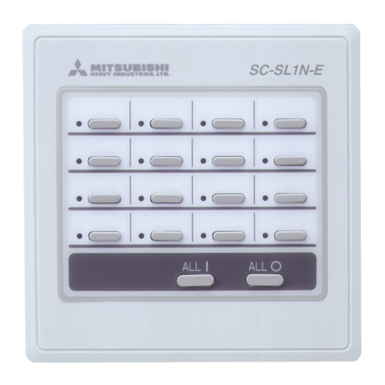
1 CENTRAL CONTROL SC-SL1N-E (1) Specifications Description CE TRAL CO TROL SC-SL1 -E Appearance Model name SC-SL1 -E Applicable model Super Link compatible indoor unit Ambient temperature at operation 0 ~ 40ûC Power supply 1 phase, AC 230 V, 50/60 Hz Power consumption 1.7W... - Page 4 (4) Electrical wiring ● Please do the grounding work. Please do not connect earth line with gas pipes, water pipes, lightning rods and grounding line of telephone. ● Please do not turn on the power supply (local switch) until all of the work is completed. ●...
- Page 5 (b) Space required for installation Lead-in wire Electrical Box (prepare on site) BuildingÕs wall M4 pilot hole Internal wall Installation opening Above 70mm Above 85mm M4 pilot hole central control The dotted lines show the installation opening section for installation on the control board (the dimensions are only an example). 1) In case of installing on the control board Please be sure to lock the control board to protect persons from electric shock.Avoid usage of heat-retaining materials and heat-insulating materials because these can result in heat buildup and adversely affect the operation of the central control.
- Page 6 4) Please connect the grounding wire. 5) Please fix the central control on 6) Please connect the signal wire Connect the grounding wire for the Electrical box or the wall by (A, B terminal) power supply wire to “Ground 1” , supplied 5 pan-head screw connect the grounding wire for signal wire to “Ground 2”.
- Page 7 (7) Setting the control target units For this central control, please set the unit number as follows. (a) Setting start address Please set initial number of units controlled by the central control. Hundreds digit Tens digit Ones digit xample 1: When initial number is 000 xample 2: When initial number is 005 SW23-1 SW22...
-
Page 8: Central Control Sc-Sl2N-E
2 CENTRAL CONTROL SC-SL2N-E (1) Specification Appearance (Close; Center & Stop all units) (Close; Center & Fan mode) Definitions of new and previous Super Link (new and previous SL) New Super Link (new SL): All units connected to the network are models compatible with New Super Link (KXE6 model or later models. - Page 10 (2) Operation and setting Operation or setting is implemented individually, in the unit of group or in a batch for air-conditioners up to 64 units or 16 groups. Item Description RU /STOP Performs operation or stop control. Operation mode Sets Auto , Cool, Dry, Fan or Heat.
- Page 11 (4) Program setting Operation program can be set in the unit of group. It is possible to register the ON/OFF time or ON time + Temperature setting at 4 times a day. Operation time can be designated in the unit of minute. (5) Administration and control Description Group setting...
- Page 12 (7) Installation procedure (a) In case of embedding in a wall, first, embed the power supply (b) Open the top case by following the procedure below. 1 Grasp the indentations on the right and left sides, and wire, signal wire, and electrical box. pull forward to open the cover downward.
- Page 13 efer to the figure below for the terminal orientation. Before connecting the wires, remove the cover of the terminal block. After the work is completed, fix the cover of the terminal block Insulation covering as before. The cover is used to prevent electric shock due to accidental contact.
- Page 14 (c) In case of installing on the control board Caution Please be sure to lock the control board to protect persons Please do not install devices that can cause the ambient from the electric shock. temperature to rise in the same control board. Also, do Avoid usage of heat-retaining materials and heat-insulating not install multiple controllers in the same control board.
- Page 15 (10) Control switch selection It is possible to change the setting as follows by settings of the PCB switches SW1 to SW10, J1, J2, and J3 on the central control. Please change the control on site as necessary. It is recommended to change the setting by using a precise driver. Switch Power failure compensation function selector Function...
-
Page 16: Central Control Sc-Sl3N-Ae, Sc-Sl3N-Be
3 CENTRAL CONTROL SC-SL3N-AE and SC-SL3N-BE (1) Specifications Description CE TRAL CO TROL SC-SL3 -AE CE TRAL CO TROL SC-SL3 -BE Appearance Model name SC-SL3 -AE SC-SL3 -BE Applicable model Super Link compatible indoor unit Ambient temperature at operation SC-SL3 -AE 0 ~ 40ûC Power supply 1 phase, 100 ~ 240 V, 50/60 Hz... - Page 17 Definitions of new and previous Super Links (new and previous SL) New Super Link (new SL): All units connected to the network are models compatible with New Super Link (KXE6 model or later models. Central controller and I/F are from “N” models.) and SL setting is unchanged from shipment (“New”...
- Page 18 (5) Schedule setting This schedule can be set by each group every one minute. It is possible to register the RUN/STOP time, operation mode, remote controller Lock/Unlock setting, temperature setting at 16 times a day.(*) Description Specify the date and select/specify the weekday, holiday, special day 1 or special day.
- Page 19 (6) Outline drawing inch color LCD Reset switch hole (¿2) Wall surface USB port Upper case setting touch panel screw (2 places) Power supply terminal block Signal wire terminal block ● Resin color: Pearl white (Close to Munsell N-8.5) ● Service space Front face: 500 mm or larger, bottom face: 200 mm or larger (7) Installation work Please install the central control after turning off the power for fear of electric shock.
- Page 20 (c) Installation procedure 1) Remove the upper case a) Take out two screws using a cross slot screwdriver. (Don’t lose the screws) b) Pull the upper case a little forward and push above. Then, upper case can be removed. > Caution > ●...
- Page 21 Wiring Specifications Power supply wire 1.25mm Local switch Super Link signal wire Shielded wire (MVVS 2 - cores) 0.75mm - 1.25mm ( ote 1, ote 2) Max. 1000m per network (Max. distance: 1000m, Total wire length: 1000m) The wire for operation output, error output, CVV CPEV (2 - cores) 0.75mm - 1.25mm emergency stop and demand input...
- Page 22 (c) Reset switch There is a switch to reset the power supply when the screen freezes. Data is never deleted with this switch. This central control will be reset in about 1 second. Operating method ¿1.5 or more Please push the button which is the inner part of the small hole of the underside of the upper case using the clip which is extended straight or the tool which is similar to that.
- Page 23 a) Maximum count number of power pulse input Watt-hour pulse unit . 1kWh/P .1kWh/P 1kWh/P 1 kWh/P 4,32 kWh/day 43,2 kWh/day 432, kWh/day 432 , kWh/day Maximum measurable watt-hour 18 kWh/h 1,8 kWh/h kWh/h 18 , kWh/h b) Maximum count number of gas pulse input as volume pulse unit 0.01m 0.05m...
- Page 24 1 In case of MULTI 1 setting: Conduct proportional distribution according to the results of a accumulated answer Hz. Accumulation is not performed when the thermo is OFF or during the Fan mode operation. Indoor unit A Indoor unit B Indoor unit C 25Hz 40Hz...
- Page 25 (d) Software overview (SC-SL3N-BE Utility) SL3N-BE Utility calculates the amount of energy consumption with air conditioner’s running data saved by SC-SL3N-BE. The amount of energy consumption is divided proportionally day by day according to the operating ratio of the air conditioner, and it is calculated as the group total amount of energy consumption for every period.
- Page 26 Small font size 4) End user agreement This software is for using SC-SL3N-BE. Mitsubishi Heavy Industries, Ltd. (MHI) permits you to use two or more copies of this software on two or more computers. This software and SC-SL3N-BE do not warrant the contents of the calculation result.
- Page 27 (e) Starting and quitting the software 1) Starting the SL3N-BE Utility ® Double-click the short-cut icon displayed on Windows desktop or select the program displayed on the Start menu. The Main Menu screen shown in Fig.1 will appear. Fig.1 Main Menu screen 2) Quitting SL3N-BE Utility Click [Exit] button, or [x] button of a title bar.
- Page 28 3) Screen changes The screen changes are shown in Fig.2. Import Accounting Import Data File Start BIN to CSV Import Conversion Main Menu Accounting Data File screen Back Back Exit Meter Group Meter Group Definition Definition Meter Group Definition screen Back Back Pulse Constant...
- Page 29 6) Calculating energy consumption a) Start the SL3N-BE utility ® Double-click the short-cut icon displayed on Windows desktop or select the program displayed on the Start menu. The Main Menu screen shown in Fig.3 will appear. Step 1: Click [Import Accounting Data File] button on this screen. Step 2: Click [Meter Group Definition] button on this screen.
- Page 30 Step 1: Import Accounting Data File (1) Beforehand, export monthly data files to a USB memory by SC-SL3N-BE. (2) Insert the USB memory in your personal computer. (3) Click a check box. Select the drive name of a USB memory, and the folder name, which exported monthly data files. (4) Specify the year and the month to calculate.
- Page 31 ● Importing Accounting Data Files SL3N-BE Utility reads a group definition file and the monthly data file of the month specified to the "year" and the "month", and the previous month, and converts them into the CSV files. The converted CSV files are the following. a) Group definition file (file name: Grp.csv) Group name, group composition b) Monthly data files...
- Page 32 Step 2: Set the Meter Group Definition SL3N-BE Utility memorizes the Meter Group Definition last time, and reads it when starting. You may skip this menu, as long as there is no change. Meter Group Definition defines to which energy system (electricity or gas) the air conditioner belongs. It is possible to assign two or more meter numbers to one air conditioner's indoor unit.
- Page 33 ● First time (1) Click [New] button and input the Meter number. (2) Click [Save] button and input the file name. (3) Click [Back] button. ● 2nd hereafter You don’t have to select this menu. However, we recommend that you check the contents of the setting whenever you calculate.
- Page 34 Step 3: Set the Pulse Constant Definition SL3N-BE Utility memorizes the Pulse Constant Definition last time, and reads it when starting. You may skip this menu, as long as there is no change. Pulse Constant Definition defines a pulse constant and the energy type (electricity or gas) for every meter. Fig.9 Pulse Constant Definition screen [New]: Push this button when you make a new definition file.
- Page 35 Step 4: Calculate Energy Consumption SL3N-BE Utility carries out proportional division calculation based on the Monthly Data Files that imported, the Meter Group Definition and the Pulse Constant Definition. And it calculates the energy consumption for every group. Fig.10 Calculate Energy Consumption screen [Calculate]: calculates the energy consumption.
- Page 36 2. When you click the check box “The electric energy consumption”, Fig.12 dialog box will appear. If you want to change the file name, the folder name and the drive name, select another drive name and the folder, and type another file name that you want.
- Page 37 Appendix 1. The image of the Monthly Energy Consumption file *** C:¥Program Files¥SLB3EUtility¥db¥MonthE0503. csv (02/05 - 03/14) Group No Group Name Basic Period [H] Overtime [H] Basic Period [kWh] Overtime [H] 1F ENTRANCE GATE 0.000 0.000 1F ENT. HALL STH 0.000 0.000 1F ENT.
- Page 38 ® Appendix 2. Dividing and Reading out the CSV file using Microsoft Excel 1) Open a new file and move a cursor to the position where you want to locate. 2) Choose the “Import External Data” menu and the “Import Data…” menu in the menu bar.
- Page 39 3) Select “All Files (*.*)” in the the “Files of type” and choose the CSV file which you want to read. Click the “Open” button. 4) Select the “Delimited” option button and the file format “Western European” in the “File origin” drop-down, and click [Next >] button.
- Page 40 6) Click the head column to exclude under the “Data preview”. 7) Click the last column to exclude, pressing [Shift] key (on keyboard), under the “Data preview”. Click the "Do not import column (skip)" in the “Column data format”, and click [Finish] button. 8) Click [OK] button.
-
Page 41: Connection Example
It is necessary, however, to use the remote controller together. utdoor unit Indoor unit SC-SL1N-E Remote controller Plural number of SC-SL1N-E can be used on a network. (This allows controlling on the basis of each floor Example 2: in an office building, for example.) utdoor unit SC-SL1N-E... - Page 42 Plural number of SC-SL2N-E may be connected to a network (indoor units up to 128 units). Since it is Example 5: possible to use mixed with SC-SL1N-E, SC-SL2N-E may be used for the central control and SC-SL1N-E for the RUN/ST P at each floor.
- Page 43 p to 128 groups, which are set optionally with the central control SC-SL3N-AE can be controlled on the Example 6: basis of each group. Note (1) A pair of center consol SC-SL3N-AE may be connected on the Super Link. Part or whole remote controllers may be abbreviated. F group G group E group...
- Page 44 Fax : (03) 6716-5926 16-5 Konan 2-chome, Minato-ku, Tokyo, 108-8215, Japan http://www.mhi-mth.co.jp/ updated 12,March,2009 Because of our policy of continuous improvement, we reserve the right to make changes in all specifications without notice. Copyright MITSUBISHI HEAVY INDUSTRIES THERMAL SYSTEMS, LTD.
Need help?
Do you have a question about the SC-SL1N-E and is the answer not in the manual?
Questions and answers