
Related Manuals for Rigol RP1003C


Summary of Contents for Rigol RP1003C
- Page 1 RIGOL User’s Guide RP1003C/RP1004C/RP1005C Current Probe Jan. 2013 RIGOL Technologies, Inc...
-
Page 3: Guaranty And Declaration
RIGOL products are protected by patent law in and outside of P.R.C. RIGOL reserves the right to modify or change parts of or all the specifications and pricing policies at company’s sole decision. Information in this publication replaces all previously ... -
Page 4: General Safety Summary
Do Not Operate With Suspected Failures. If you suspect damage occurs to the instrument, have it inspected by qualified service personnel before further operations. Any maintenance, adjustment or replacement especially to circuits or accessories must be performed by RIGOL authorized personnel. RP1003C/RP1004C/RP1005C User’s Guide... - Page 5 Electrostatic Prevention. Operate in an electrostatic discharge protective area environment to avoid damages induced by static discharges. Always ground both the internal and external conductors of the cable to release static before connecting. RP1003C/RP1004C/RP1005C User’s Guide...
-
Page 6: Safety Terms And Symbols
CAUTION indicates a potential damage to the instrument or other property might occur. Symbols on the Product. These symbols may appear on the product: Double Safety Protective Chassis Test Insulation Warning Earth Ground Ground Terminal RP1003C/RP1004C/RP1005C User’s Guide... -
Page 7: Precautions
Make sure that the power supply has a protective earthing with double-insulation construction. Make sure that the measuring instrument connected to the output terminal of the current probe is equipped with a protective earthing with double-insulation construction. RP1003C/RP1004C/RP1005C User’s Guide... - Page 8 Otherwise, short-circuit current will flow through the power adaptor or current probe from the ground terminal, which could cause an electrical accident or damage. RP1003C and RP1004C: × RP1003C/RP1004C/RP1005C User’s Guide...
- Page 9 Keep the current sensor closed, except when clamping it onto the conductor to be measured. The mating surface of the core can be scratched when it is open. Avoid stepping on or pinching the cable, which could damage RP1003C/RP1004C/RP1005C User’s Guide...
- Page 10 Do not store or use the device where it could be exposed to direct sunlight, high temperature, humidity or condensation. Under such conditions, the device might be damaged and insulation may deteriorate so that it no longer meets specifications. VIII RP1003C/RP1004C/RP1005C User’s Guide...
-
Page 11: General Inspection
The consigner or carrier shall be liable for the damage to probe resulting from shipment. RIGOL would not be responsible for free maintenance/rework or replacement of the unit. Inspect the probe In case of any damage, or defect, or failure, notify your RIGOL sales representative. RP1003C/RP1004C/RP1005C User’s Guide... -
Page 12: Table Of Contents
Specifications ................16 Technical Parameters ............... 16 General Specifications .............. 19 Appendix ................. 21 Appendix 1 Amplitude Characteristics ........21 Appendix 2 Relation between Max Input Current and Frequency . 23 Appendix 3 Input Impedance (Typical) ........25 RP1003C/RP1004C/RP1005C User’s Guide... -
Page 13: Current Probe Overview
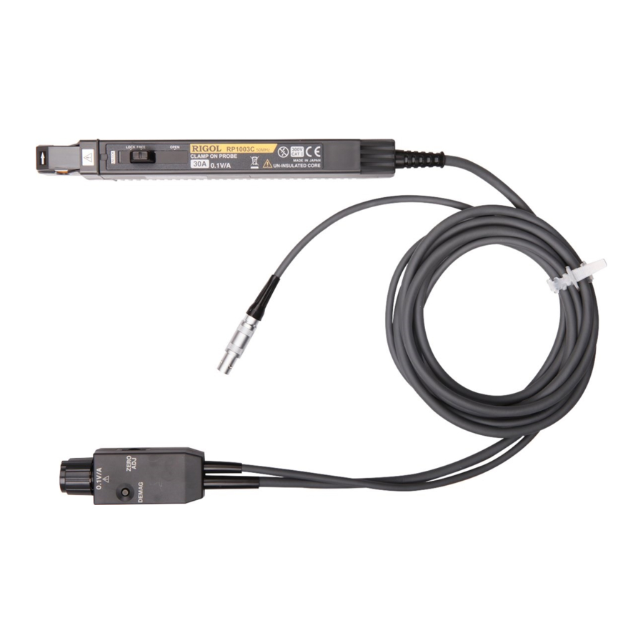
RIGOL Current Probe Overview RP1003C, RP1004C and RP1005C current probes can detect the current flowing through the conductor and convert it to voltage that can be displayed on and measured by the measuring instrument. Main Features: Highly accurate current detection ... - Page 14 RP1003C Parts Overview Current Direction Terminator Gain On/Off Indication Indication Power Supply Cable Sensor Cable Figure 1 RP1003C Parts Note: For more information of parts 1 to 7 in the figure above, refer to the introductions on page 4. RP1003C/RP1004C/RP1005C User’s Guide...
- Page 15 RP1004C Parts Overview Current Direction Gain On/Off Indication Terminator Indication Power Supply Cable Sensor Cable Figure 2 RP1004C Parts Note: For more information of parts 1 to 7 in the figure above, refer to the introductions on page 4. RP1003C/RP1004C/RP1005C User’s Guide...
- Page 16 For RP1003C and RP1004C, there are OPEN, FREE and LOCK indications on one side of the slide switch. The on/off status of the current sensor is related to the position of the slide switch.
- Page 17 When beginning measurement, after demagnetizing always carry out zero adjustment to adjust the baseline to zero. 5. Coarse Adjustment Trimmer (only applicable to RP1003C and RP1004C) When adjustment is not possible within the range of zero adjustment dial, use a nonconductive screwdriver to (such as RP1003C/RP1004C/RP1005C User’s Guide...
- Page 18 Note: For RP1003C and RP1004C, 0.1V/A on the output connector is the gain when the input impedance of the measuring instrument is 1MΩ; the corresponding gain is 1/2×0.1V/A=0.05V/A when the input impedance of the measuring instrument is 50Ω.
-
Page 19: To Use The Current Probe
Turn off the power adaptor and connect it to the power supply. Note: The voltage of the power supply used should match the rated supply voltage of the power adaptor. Turn on the power adaptor and check whether the power indicator lights. RP1003C/RP1004C/RP1005C User’s Guide... -
Page 20: Demagnetizing
Forcibly pulling the connector without releasing the lock or pulling on the cable can damage the terminator. Make sure the current sensor is locked (for RP1003C and RP1004C, RP1003C/RP1004C/RP1005C User’s Guide... - Page 21 Note: Do not demagnetize the current probe when it is clamping a conductor to be measured. Demagnetizing causes current to flow into the conductor, which may damage the parts in the circuit to be measured. RP1003C and RP1004C: Demagnetizing × RP1005C: Demagnetizing ×...
-
Page 22: Zero Adjustment
Make measurements after the above operations are finished. Open the current sensor by pushing the slide switch in the direction of the arrow as shown in the figure below (for RP1003C and RP1004C, the slide switch should be at the OPEN position; for RP1005C, UNLOCK should be displayed on the slide switch and LOCK should disappear). - Page 23 Indication Lock the current sensor by pushing the slide switch in the direction of the arrow as shown in the figure below (for RP1003C and RP1004C, the slide switch should be at the LOCK position; for RP1005C, you need to first press the current probe to close the current sensor and then push the slide switch until LOCK is displayed and UNLOCK disappears).
-
Page 24: Precautions During Measurements
The maximum continuous input range is based on the heat that is internally generated during the measurement. Note that the input current should not exceed this range; otherwise, the current probe might be damaged. RP1003C/RP1004C/RP1005C User’s Guide... - Page 25 10kHz or higher near the current sensor (as shown in the figures on the next page). Current flowing in the conductor nearby may heat up the sensor and cause its temperature to rise, leading to damage to the current sensor. RP1003C/RP1004C/RP1005C User’s Guide...
- Page 26 RP1005C: Be sure to use the slide switch to open the current sensor. For RP1003C and RP1004C, please do not press the upper core in the direction of the arrow as shown in the figure below to avoid damaging the internal structure of the slide switch.
- Page 27 RIGOL RP1003C and RP1004C: High × Signal Load √ Source RP1005C: High × Signal Load Source √ RP1003C/RP1004C/RP1005C User’s Guide...
-
Page 28: Specifications
30 minutes under the specified operating temperature (10℃ to 30℃) and humidity (0%RH to 80%RH). Technical Parameters RP1003C: DC to 50MHz (-3dB), refer to Appendix 1 Bandwidth Amplitude Characteristics (RP1003C) Rise Time ≤7ns Linear Response 30Arms, refer to Appendix 2 Relation Range of Input... - Page 29 66Hz, within the linear response range of the input current) ≤2.5mArms (for 20MHz band measuring Noise instrument) Refer to Appendix 3 Input Impedance Input Impedance (Typical) (RP1004C) ≤±2% (0℃ to 40℃ temperature, input of Gain Accuracy Drift RP1003C/RP1004C/RP1005C User’s Guide...
- Page 30 ±2.0%rdg, 150A to 300A peak (DC and 45Hz to 66Hz) ≤25mArms (for 20MHz band measuring Noise instrument) Refer to Appendix 3 Input Impedance Input Impedance (Typical) (RP1005C) ≤±2% (0℃ to 40℃ temperature, input of Gain Accuracy Drift 55Hz, 150A) Rated Power 5.5W RP1003C/RP1004C/RP1005C User’s Guide...
-
Page 31: General Specifications
Probe 176mmx69mmx34mm Dimensions RP1003C: approx. 6.9mmx2.5mmx1.6mm RP1004C: approx. Terminator 6.9mmx2.5mmx1.6mm RP1005C: approx. 6.9mmx2.5mmx1.6mm Maximum RP1003C: approx. 5mm Dimensions of RP1004C: approx. 5mm Conductor to be RP1005C: approx. 20mm Measured Current RP1003C: approx. 150cm Sensor RP1004C: approx. 150cm Cable RP1005C: approx. 200cm... - Page 32 -10℃ to +50℃, 0 to 80%RH Temperature and Humidity Location for Use Indoor, altitude up to 2000m Electromagnetic EN61326 Compatibility RP1003C: CAT I (anticipated transient voltage 1500V) Measurement RP1004C: CAT I (anticipated transient voltage Category 1500V) RP1005C: CAT II, CAT III (anticipated transient...
-
Page 33: Appendix
RIGOL Appendix Appendix 1 Amplitude-frequency Characteristics RP1003C: Frequency:Hz 100M RP1004C: 100M Frequency: Hz RP1003C/RP1004C/RP1005C User’s Guide... - Page 34 RIGOL RP1005C: 100k 100M Frequency: Hz RP1003C/RP1004C/RP1005C User’s Guide...
-
Page 35: Appendix 2 Relation Between Max Input Current And Frequency
RIGOL Appendix 2 Relation between Max Input Current and Frequency RP1003C: 10M 100M Frequency: Hz 100k RP1004C: 10M 100M Frequency: Hz 100k RP1003C/RP1004C/RP1005C User’s Guide... - Page 36 RIGOL RP1005C: 100k Frequency: Hz RP1003C/RP1004C/RP1005C User’s Guide...
-
Page 37: Appendix 3 Input Impedance (Typical)
RIGOL Appendix 3 Input Impedance (Typical) RP1003C: 100m Frequency: Hz 100k 10M 100M RP1004C: 100m 100M Frequency: Hz 100k RP1003C/RP1004C/RP1005C User’s Guide... - Page 38 RIGOL RP1005C: 0.01 0.001 Frequency: Hz 100k RP1003C/RP1004C/RP1005C User’s Guide...
Need help?
Do you have a question about the RP1003C and is the answer not in the manual?
Questions and answers