Table of Contents
Advertisement
Advertisement
Table of Contents

Subscribe to Our Youtube Channel
Related Manuals for Iso-Tech SLM 52N


Summary of Contents for Iso-Tech SLM 52N
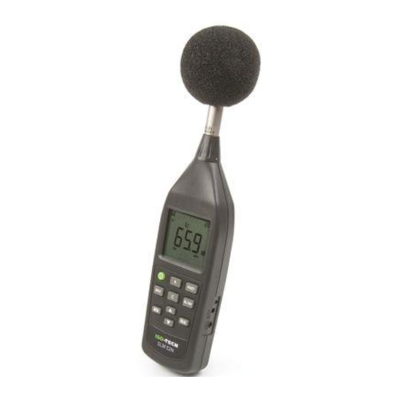
- Page 1 Instruction Manual SLM 52N Sound Level Meter...
-
Page 2: Table Of Contents
CONTENTS Title Page 1. INSTRUMENT CARE ..................1 2. FEATURES..................... 2 3. MEASUREMENT PARAMETERS..............2 4. SPECIFICATIONS ..................2 5. CONTROLS AND FUNCTIONS ..............9 6. DISPLAY DESCRIPTION ................11 7. PREPARATION FOR USE ................12 8. CALIBRATION PROCEDURE ..............14 9. -
Page 3: Instrument Care
1. INSTRUMENT CARE Do not attempt to remove the mesh cover from the microphone as this will cause damage and affect the accuracy of the instrument. Protect the instrument from impact. Do not drop it or subject it to rough handling. Transport it in the supplied carrying case. -
Page 4: Features
2. FEATURES The ISO-TECH SLM 52N Sound Level Meter complies with the requirements of IEC 61672-1: 2002 standard for a Class 2 instrument. The instrument contains several features which permit sound level measurements under a variety of conditions. Features include: Ease of use. - Page 5 Measurement functions: • Main processing functions Sound level: Current time-weighted sound pressure level A or current time- weighted sound pressure level C Maximum time-weighted sound pressure level A or Maximum time-weighted sound pressure level C • Total range: 30 to 130dB A & C weighted •...
- Page 6 RANGE: 50 – 110 dB. Test starting point 84 dB for all weightings and frequencies except 31.5Hz A-weighted, for which the starting point is 64 dB. FREQUENCY L.O.R L.O.R WEIGHTING WEIGHTING 31.5 50.0 – 70.6 50.0 – 107.0 1000 50.0 – 110.0 50.0 –...
- Page 7 Reference incidence direction: Perpendicular to the front of the microphone diaphragm. • Calibration: Acoustic using calibrator ISO-TECH SLC 1356, B&K 4231 or equivalent. Calibration check frequency is 1000Hz. Nominal calibration level for the free field: 94.1dB Nominal calibration level for the diffuse field: 94.0dB •...
- Page 8 Frequency Response 1000 2000 5000 10000 20000 (Hz) Freq 31.5 1000 2000 4000 8000 units +0.6 +0.8 +0.2 +0.0 +0.8 +1.3 +3.0 Typical free-field response 0° ° ° ° incidence Freq 31.5 1000 2000 4000 8000 units +0.1 +0.4 +0.5 -0.2 +0.2 -0.5...
- Page 9 Display LCD • Display screens: 4 digit numerical indication of sound level, from 30.0 to 130.0dB with 0.1dB resolution. Bar-graph indication of current sound level with 1dB resolution. Sound level range indicator: 30–90dB, 40–100dB, 50–110dB, 60–120dB or 70–130dB in five ranges. Memory and Read indicator : 99 sets •...
- Page 10 Compliance with standards: • indicates compliance with applicable European Union Directives. • EMC Emission: IEC 61000-6-3, Generic emission standard for residential, commercial and light industrial environments. No significant emissions from the instrument. IEC 61672-1, Instrumentation standard classification group X and performance class 2 sound level meter.
-
Page 11: Controls And Functions
5. CONTROLS AND FUNCTIONS 1. Microphone and preamplifier: The MC-21 microphone capsule is connected to the AP-21 preamplifier for normal operation. The microphone capsule may be carefully removed from the preamplifier and substituted with the appropriate electrical impedance (See sect. 4. “Specifications”) for electrical verification of the instrument. 2. - Page 12 7. MEM button : Press to store measurement data sets in memory. 8. READ button : Press to read the stored data sets in memory, press again to exit read mode. 9. ▲ ▲ ▲ ▲ ▼ ▼ ▼ ▼ buttons : Level range buttons : select the level range for the measurement.
-
Page 13: Display Description
6. DISPLAY DESCRIPTION Sound level range indicator (5 ranges): 30–90dB, 40–100dB, 50–110dB, 60–120dB and 70–130dB 2. Bar graph shows the current sound level (1dB resolution). : Under-range indicator. Un : Under-range indicator for processed value. 5. A, C: “A” Frequency weighting or “C” Frequency weighting indicator. Ov : Over-range indicator for processed value. -
Page 14: Preparation For Use
7. PREPARATION FOR USE Power Supply The instrument can be powered by internal batteries, or for extended operation by an optional external 9V DC supply such as a suitable AC mains adapter or battery pack. Rechargeable batteries may be used in the instrument, but cannot be recharged when fitted as the instrument is not designed to recharge batteries. - Page 15 3. Windscreen When making measurements outdoors in strong winds or when measuring air conditioning equipment or similar, wind noise and strong air movements at the microphone can cause measurement errors. Such effect can be reduced by using the windscreen. Windscreen 4.
-
Page 16: Calibration Procedure
8. CALIBRATION PROCEDURE Most national standards recommend that you calibrate your sound level meter before each set of measurements and check the calibration after each set. The procedure to check/adjust the displayed sound level in response to acoustic calibrator types SLC 1356 or B&K 4231 (or equivalent) is as follows: 1. -
Page 17: Store Operations
4. When performing measurement according to IEC or other standards, the frequency weighting and time weighting setting required by the standard should be selected. 5. Press the “ ▲ ▲ ▲ ▲ and ▼ ▼ ▼ ▼ ” buttons to select desired level range. Choose a setting in which the bar graph indication registers approximately the middle of the range. -
Page 18: Output Connectors
11. OUTPUT CONNECTORS 3.5φ Plug Wiring Connection Ac output Common output Dc output AC Output: An AC signal corresponding to the frequency-weighted signal is available at this connector. Output voltage: 1Vrms±100mVrms (scale upper limit) Output impedance: approx. 5kΩ Load impedance:≧ 1MΩ The output voltage when the instrument is in calibration mode (-6dB from scale upper limit, 1000Hz sine wave) is 0.5Vrms. -
Page 19: Typical Frequency Response Due To Case Reflections At
Absolute effect at 1000Hz = 0.0 dB Case reflections for an ISO-TECH 52N meter fitted with an MC-21 microphone as per IEC 61672-1 and IEC 60651, relative to 1000Hz. 15. TYPICAL FREQUENCY RESPONSE OF 65mm WINDSCREEN AT 0°... -
Page 20: Directional Characteristics Of The Complete Instrument
16. DIRECTIONAL CHARACTERISTICS OF THE COMPLETE INSTRUMENT The directional characteristics of a microphone give a measure of its differing sensitivity for sound waves arriving from various angles. Since the pre-polarized condenser microphone used in the instrument is a pressure-sensitive type, it should be equally sensitive in all directions. - Page 21 10.0 -5.0 -10.0 -15.0 -20.0 -25.0 Directional characteristics for frequency equal to 2000Hz 10.0 -5.0 -10.0 -15.0 -20.0 -25.0 Directional characteristics for frequency equal to 4000Hz EN-19...
-
Page 22: Appendix A Frequency Weighting Network
-20.0 -25.0 Directional characteristics for frequency equal to 8000Hz 17. APPENDIX A FREQUENCY WEIGHTING NETWORK The SLM 52N provides frequency weightings A, and C. The electrical characteristics of the weighting network at AC output connector are as shown below. EN-20... -
Page 23: Appendix B Rms Detection Circuit And Time Weighting
The human perception of a sound depends not only on the sound pressure level, but also on the frequency. At high or low frequencies, a sound is felt to be less loud than a sound of equal level in the midrange. The frequency weighting A compensates for this effect and produces measurement results which are close to the perceived sound level. - Page 24 The time weighting network of the sound level meter performs index averaging on the square of the sound pressure signal. The equivalent circuit is shown at right. τ τ τ τ is the time constant, which equals CR. The response of the index averaging circuit to a single burst signal is shown below. = C R :Input voltage :Output voltage...
-
Page 25: Appendix C Influence Of Background Noise
19. APPENDIX C INFLUENCE OF BACKGROUND NOISE When measuring a certain sound in a certain location, all other sounds present at that location except the measurement target sound are background noise (also called ambient noise or dark noise). Since the sound level meter will display the combination of target sound and background noise, the amount of background noise must be taken into consideration when determining the level of the target sound.
Need help?
Do you have a question about the SLM 52N and is the answer not in the manual?
Questions and answers