
Subscribe to Our Youtube Channel
Related Manuals for Iso-Tech SLA-1358


Summary of Contents for Iso-Tech SLA-1358
- Page 1 Sound Analyser ISO-TECH Real Time 1/1 & 1/3 Octave band Analysis SLA-1358 INSTRUCTION MANUAL...
-
Page 2: Table Of Contents
CONTENTS Title Page SAFETY INFORMATION ........1 GENERAL INFORMATION & FEATURES ... 2 III. SPECIFICATIONS..........2 CONTROLS AND FUNCTIONS ......5 4-1 Parts description...........5 4-2 Operation keys .............7 4-3 Measurement screen..........10 CALIBRATION PROCEDURES ......11 MEASUREMENT PREPARATION...... 12 VII. SETTING THE DATE AND TIME ......12 VIII. -
Page 3: Safety Information
I. SAFETY INFORMATION q Read the following safety information carefully before attempting to operate or service the meter. q Use the meter only as specified in this manual, otherwise the protection provided by the meter and general operation may be impaired. q Environmental conditions ... -
Page 4: General Information & Features
II. GENERAL INFORMATION & FEATURES The SLA 1358 meter allows digital 1/1-octave and 1/3-octave analysis in real time. q Five measured parameters SPL (Sound Pressure Level), Leq (Equivalent Continuous Sound Pressure Level), L (Sound Exposure Level), Lmax (Maximum Sound Pressure Level), Lmin (Minimum Sound Pressure Level) q RS-232 interface for PC connection q Data Logger function... - Page 5 q Accuracy : ±1.5dB (ref 94dB @1kHz) q Measurement Frequency range : 25Hz – 10KHz q Dynamic range : 100dB (Sound level meter mode) 70dB (Frequency analysis mode) q Measurement range : 30dB – 130dB q Sound Pressure Level range: Sound level meter mode (display range 100dB) : 30 –...
- Page 6 q AC output : 2 Vrms at FS (full scale). output impedance approx. 600Ω. q DC output : 10mV/dB. output impedance approx. 100Ω. q Power : Qty 4, C size 1.5V (LR14) alkaline batteries. External DC power supply : 6 Vdc, 1A. q Battery life : Approx.
-
Page 7: Controls And Functions
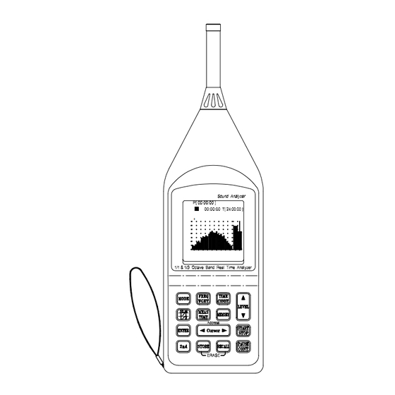
IV. CONTROLS AND FUNCTIONS 4-1 Parts description FAST 65.2 dB 31.5 [ 1 / 3 OCT ] 01 / 06 / 19 14:26:39 SOUND ANALYZER 1/1 & 1/3 OCTAVE BAND IEC 651 IEC 804 TYPE 2 IEC 1260 CLASS2 ACCURACY : ¡ Ó 1 .5dB IEC LR14 1.5V X 4 1. - Page 8 5. Power switch. This sliding switch serves to turn the unit on and off. 6. Calibration adjustment knob. Used to carry out manual calibration, using the supplied adjustment screwdriver. 7. DC 6V jack. For use with AC power adapter. 8. DC output jack. A DC signal corresponding to the sound pressure level is available at this output.
-
Page 9: Operation Keys
4-2 Operation keys a.) MODE key Calls up the various processing results on the display. Display options are sound pressure level (L), equivalent continuous sound pressure level (Leq), sound exposure level (L ), maximum sound pressure level (Lmax), and minimum sound pressure level (Lmin). - Page 10 d.) 5LEVEL6 Used to select the sound pressure level ranges on 1/1 and 1/3 octave band frequency analysis mode. (20~90dB, 30~100dB, 40~110dB, 50~120dB and 60~130dB, total 5 ranges) e.) SLM/ 1/1/ 1/3 key This key switches the operation mode between sound level meter (SLM), 1/1-octave frequency analysis (1/1), and 1/3-octave frequency analysis (1/3).
- Page 11 Press to start and to terminate the Leq, L , Lmax and Lmin sound pressure level measurement. k.) PAUSE/CONT key Used to temporarily pause measurement ( display ) or resume (4display ). l.) 2nd key Press to shift key to second function. m.) STORE key In manual memory mode, stores the measured data into the memory.
-
Page 12: Measurement Screen
4-3 Measurement screen 1. Sound pressure level measurement screen FAST ] 01 / 07 / 27 14:26:39 2. 1/1-octave analysis screen The bar display on the LCD represents the 1/1-octave analysis result. From left, the bars correspond to 31.5, 63, 125, 250, 500, 1k, 2k, 4k, 8kHz. -
Page 13: Calibration Procedures
75.2 dB 31.5 [ 1 / 3 OCT ] 01 / 07/ 27 14:26:39 V. CALIBRATION PROCEDURES Using a standard acoustic calibrator such as the ISO-TECH SLC 1356 1. Make the following switch settings. Display : SLM (L Time weighting : FAST 2. -
Page 14: Measurement Preparation
VI. MEASUREMENT PREPARATION 1. Battery installation. Remove the battery cover on the back of the meter and insert batteries (4 x 1.5V size C). Note : Take care to observe battery polarity. 2. Battery replacement. When the battery voltage drops below the operating voltage, LBATT appears and flashes on the display. -
Page 15: Sound Pressure Level Measurement
VIII. SOUND PRESSURE LEVEL MEASUREMENT 8-1 Technical notes 1. The decibel (dB). The range over which the human ear responds to sound pressure (noise) is extremely large ; 20mPa (the threshold of hearing) to 100 Pa (the threshold of pain). The measurement of sound pressure is made manageable by use of the decibel, which is logarithmic. -
Page 16: Instantaneous Sound Pressure Level Measurement
but compressed in to 1 second. This allows the total sound energy of an event, such as train passing a platform, to be evaluated. Another event, such as the next train, which lasts for a different amount of time can be measured in the same way. - Page 17 FAST FAST 75.2 dB 75.2 dB Hz 31.5 31.5 [ 1 / 1 OCT ] 01 / 07 / 27 14:26:39 [ 1 / 3 OCT ] 01 / 07/ 27 14:26:39 3. Use the FREQ WGHT key to select the desired L or L frequency weighting setting.
-
Page 18: Measurement
8-3 L and L measurement To perform a measurement, carry out the following steps. 1. Set the power switch to ON and wait until the measurement screen appears. 2. Press the MEAS TIME key, setting the preset measurement time for a fixed time period (know as the integral time), after which measurement automatically stops. - Page 19 3. Use the SLM/ 1/1/ 1/3 key to select desired SLM, 1/1 or 1/3 octave band sound pressure level measurement screen. 4. Use the FREQ WGHT key to select the desired L or L frequency weighting setting. 5. Use the TIME CONST key to select the desired FAST or SLOW time constant setting.
-
Page 20: Memory Function
IX. MEMORY FUNCTION The SLA 1358 incorporates a memory that allows manual and automatic storing of measured data. Stored measurement results can be displayed by pressing the RECALL key. MANU (manual store): Measured data and processing results can be stored manually by the operator. - Page 21 By repeating this procedure, more data can be stored in memory. 5. Press MEMORY key again to exit the memory mode.
-
Page 22: Reading From Memory
9-2 Reading from memory 1. Press MEMORY key, enter memory mode, display M [****]. 2. Press RECALL key, display R [****] record number and data value. If no data records are stored in the memory, the RECALL key will not activate. FAST 75.2 dB 31.5... -
Page 23: Automatic Data Storage In Memory
9-3 Automatic data storage in memory Before auto store of data, the record interval period must be set. When in auto store data mode, the user cannot view other measurement parameters. 1. Setting record interval period : The record interval period default value is “0”. - Page 24 6. Press the START/STOP key to activate automatic data recording to memory. The top of the screen should show “ S Auto ” and the4 annunciator. FAST 75.2 dB 31.5 [ 1 / 1 OCT ] 01 / 07 / 27 14:26:39 CAUTION : When in auto store mode, the parameter setting cannot be changed (such as frequency weighting, time constant, 5LEVEL6 ).
-
Page 25: Erase Memory Data
9-4 Erase memory data 1. When the instrument memory is full, the FULL annunciator appears in the upper right hand corner of the screen. ID No: 00001358 Ver: 0.10 ALL Memory are Erased !! FAST SOUND LEVEL METER 1/1 & 1/3 Octave Band Real-Time Analyzer ] 01 / 07 / 27 14:26:39 Self-Testing..OK!! - Page 26 RS Components UK PO Box 99, Corby Northants, NN17 9RS Tel: +44 (0)1536 201234 Fax: +44 (0)1536 405678 Sep-2002...
Need help?
Do you have a question about the SLA-1358 and is the answer not in the manual?
Questions and answers