
Related Manuals for Mitsubishi PLK-E1010


Summary of Contents for Mitsubishi PLK-E1010
- Page 1 MITSUBISHI Industrial Sewing Machine TECHNICAL MANUAL MECHANICAL VERSION Electronic Pattern Sewing Machine PLK-E1010 Model A180E494P01...
- Page 2 All information in this technical manual are subject to change without notice. MITSUBISHI ELECTRIC CORPORATION has all the copy rights on this technical manual. Reprinting the parts or all of this technical manual is not allowed without permission.
- Page 3 ENVIRONMENT STANDARD Caution For avoiding the sewing machine from the troubles, please do not operate the sewing machine under the following conditions. Temperature and humidity (a) During operating : The atmosphere temperature should not exceeded more 35ºC (95ºF) or less 5ºC(41ºF). (b) During transportation : The atmosphere temperature should not exceeded more 55ºC (131ºF) or less -10ºC (18ºF).
-
Page 4: Table Of Contents
CONTENTS 1. STRUCTURE OF THE MACHINE ······································································ 2. SPECIFICATION ·································································································· 3. INSTALLATION ··································································································· 3-1. Preparation of the table ··················································································· 3-2. Preparation for the steel stand ········································································ 3-3. Installation of the motor ··················································································· 3-4. Installation of the control box ·········································································· 3-5. Connection of the operation panel ·································································· 3-6. - Page 5 7. STANDARD ADJUSTMENT ··············································································· 7-1. Adjustment of the needle bar position ····························································· 19 7-2. Adjustment of the position between the needle and the shuttle hook ·············· 20 7-3. Adjustment of the clearance between the shuttle hook and the needle ··········· 21 7-4.
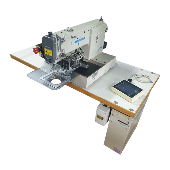
- Page 6 1. STRUCTURE OF THE SEWING MACHINE PLK-E1010 electronic pattern sewing machine is constructed with the following main parts. 1 Sewing machine head 2 Thread stand 3Operation Panel 4 Control Unit 5Halt switch 6 Work holder foot switch 7 Start foot switch 8Work holder pedal 9Steel stand *Limi-servo motor From the library of Superior Sewing Machine &...
-
Page 7: Specification
2. SPECIFICATION (1) Specification of mechanism Sewing area : X-Direction (left/right) Y-Direction (fore/backward) 100mm 100mm Maximum sewing speed : 2500 rpm Sewing speed : 10 steps variable from 200 to 2500 rpm Stitch length : 0.1 to 12.7 mm (Adjustable from 0.1mm to 12.7mm by 0.1mm resolution) Stitch type : Single needle lock stitch Needle bar stroke... -
Page 8: Installation
Please do not operate the sewing machine with excessive modifications from the standard specification 3-1 Preparation of the table If the table is not MITSUBISHI original, the thickness of the table is required to have 40mm more. And please refer to the cut out table drawing for your own preparation. -
Page 9: Installation Of The Power Switch
3-6 Installation of the power switch If the power switch is purchased without assembling to the table, the power switch has to be attached with the following procedure. (1) Mount the power switch (NO.1) with the wood screw (NO.2) underneath the table as shown on the figure. -
Page 10: Installation Of The Oil Pan
3-8 Installation of the oil pan (1) Assemble the oil pan (NO.1) and bottle (NO.2), which enclosed in the accessory box. (2) Insert the oil bottle (NO.2) into the tabletop cut-out hole (NO.3), which has much shorter distance from the bottle center to the front. (3) Install the oil pan (NO.1) parallel with the table front edge. -
Page 11: Putting Across The V-Belt
3-10 Putting across the V-belt Caution For the safety, when tilt or raise the sewing machine head, please make sure to hold the sewing machine head with both hands by two people at least. (1) Tilt the sewing machine head to the left, and hold it with the head rest. (2) Put the V-belt (NO.4) across the sewing machine pulley and the motor pulley with passing it through the slit on the tabletop. -
Page 12: Connection Of The Electric Cables
3-11 Connection of the electric cables (1) Connect the white color cable (NO.1) and the black color cable (NO.2) across the printed circuit board unit connectors (NO.4) on the sewing machine head (NO.3) rear face and the connectors (NO.5) on the control box. These cables are enclosed in the accessory box. (2) Remove the stepping motor cover (NO.8) from sewing machine head (NO.3). -
Page 13: Installation Of The Belt Cover
< Back side view of the Control box > Connect with Main motor cable Power supply cable Stepping motor cable Solenoid output cable RS-232C (optional use) Operation panel cable Extension I/O cable Input signal cable Foot switch cable 3-12 Installation of the belt cover Put the large belt cover (NO.2) on the sewing machine head with the set screws (NO.1 &... -
Page 14: Installation Of The Thread Stand
3-13 Installation of the thread stand (1) Assemble thread stand with instructions enclosed in the packing. (2) Fit the thread stand (NO.1) in the thread stand hole on the tabletop. (3) Fix the thread stand (NO.1) firmly from the rear side of the table with tightening the nut (NO.4) and the washers (NO.2, 3). -
Page 15: Lubrication
4. LUBRICATION Caution Please make sure to turn power switch OFF before oiling. Please make sure to put some oil before starting the operation of the brand new machine or Please use high quality white machining oil. NOTE 4-1 Filling the oil tank Pour the oil through the oil hole (NO.1) to the oil tank (NO.2) on the machine arm. -
Page 16: Proper Operation
5. PROPER OPERATION 5-1 Loading the system software to the control box When the brand new machine is operated first time or when the control box is adjusted for the repairing, the system software has to be loaded to the control box. For this loading, please take the following procedure. -
Page 17: Threading The Upper Thread
5-3 Threading the upper thread Caution Please make sure to turn the power switch OFF before threading the upper thread. Please thread the upper thread with referring to the below figures. 5-4 Winding the bobbin thread Caution Please make sure to pull the upper thread out of the needle before winding the bobbin thread. - Page 18 (6) Press the key, then work holder moves to home position. (7) Press key on the operation panel. Then presser foot goes down automatically, and wind mode window will be appeared. (8) Step on the black color foot switch (NO.7) again to make work holder down.
-
Page 19: Setting The Bobbin
5-5. Settling the bobbin (1) Set the bobbin (NO.2) into the bobbin case (NO.1). (2) Pull the bobbin thread (NO.3) into the slit (NO.4) and pass the thread through the thread hole (NO.5). (3) At this time, pull the bobbin thread (NO.3) then, check with the bobbin (NO.2) if it is rotated to the arrow direction. -
Page 20: Proper Sewing
6. PROPER SEWING 6-1. Operation of the halt switch If an incident such as a thread breakage, needle breakage and any other incidents are happened during the sewing operation, please hit immediately the halt switch. The sewing machine running is stopped instantly. Caution Before start the sewing operation, please make sure the location of the halt switch and keep it in mind the function and how to use it. -
Page 21: The Sewing Operation
Caution Depending on the shape of the work holder, the collision may be happened with the work holder and the presser foot while the work holder is on the way back to the home position. For avoidance of this accident, before starting the sewing operation, program the work holder returning home with the operation panel of the control box to trace the sewing... -
Page 22: Adjustment Of The Thread Tension
(6) Step on the gray color start switch (NO.5). The sewing machine starts the sewing. (7) After finished the sewing, the work holder is lifted automatically then, the sewing material is released. 6-3. Adjustment of the thread tension The thread tension between the upper and bottom thread should be balanced in the best condition. - Page 23 ○ ○ ○ ○ × × × × × × × × Well balanced The upper thread is tight The upper thread is loose tension or the bobbin thread is loose or the bobbin thread is tight (1) Bobbin thread tension Adjust the bobbin thread tension with the thread tension adjusting screw (NO.2) on the bobbin case (NO.1).
-
Page 24: Standard Adjustment
7. STANDARD ADJUSTMENT Caution Please make sure to turn the power switch OFF before adjust the sewing machine. If the adjustment is required under the power switch is ON, keep the start foot switch away from the foot. Be careful not to be wounded by the needle or the inner hook point. Please make sure to put the safety guards (Eye guard, Belt guard, Link cover and finger guard etc.) back on the original location after the sewing machine adjustment. -
Page 25: Adjustment Of The Position Between The Needle And The Shuttle Hook
7-2. Adjustment of the position between the needle and the shuttle hook (1) Turn the power switch OFF. (2) Turn the sewing machine pulley by hand then, move up the needle bar (No.1) from the lowest position and stop it at the position (No.2) where the needle bar timing mark C is matched to the needle bar bushing bottom line. -
Page 26: Adjustment Of The Clearance Between The Shuttle Hook And The Needle
7-3. Adjustment of the clearance between the shuttle hook and the needle (1) Please take the same procedures as above paragraph 7-2. from (1) to (5). (2) Loosen the outer hook setscrew (No.3) and turn the eccentric pin (No.4) so that the clearance between the shuttle hook point and the needle becomes 0.05~0.1mm. -
Page 27: Adjustment Of The Thread Guide
7-5. Adjustment of the thread guide (1) Remove the E-shaped snap ring (No.3) which is engaging the movable knife (No.2) and the link (No.1) then, loosen the setscrews (No.4) and remove the sliding plate (S)(No.5). (2) Loosen the setscrews (No.10) and move the thread guide (No.6) to the position where the needle center line (No.8) divides the needle groove (No.7) evenly and the rear side line (No.9) of the needle is aligned with the shoulder (No.9) of the thread guide (No.6). - Page 28 (1) Turn the power switch OFF. (2) Remove the face plate (No.1) and the link cover (No.2). (3) Turn the sewing machine pulley by hand and stop the needle bar (No.3) at the lowest position. At this time, make sure the setscrew (No.5) of the eccentric cam (No.4) is positioned right beside the center line of the upper shaft.
- Page 29 [NOTE] If the thickness of the sewing material changes very often, it is recommended to take the easy way for the adjustment of the presser foot position with the method that change only the fixed position of the presser foot after fixed the presser foot bar at higher position.
-
Page 30: Adjustment Of The Presser Foot Lift During The Sewing
7-6-3. Adjustment of the presser foot timing [NOTE] The presser foot up and down movement during the sewing synchronizes with the needle up and down movement. With changing this synchronized timing to the sewing materials, the skip stitches can be prevented or the seam tightness can be improved. For example, the delay of the presser foot timing against the needle movement prevents the skip stitches especially to the thin materials, and the advance of the presser foot timing can improve the seam tightness especially to the thick materials. -
Page 31: Adjustment Of The Wiper
7-7. Adjustment of the wiper (1) Loosen the wiper setscrew (No.3) and adjust the wiper (No.1) to be positioned where the wiper (No.1) passes under the needle point (No.2) with about 2 mm clearances right after the sewing machine is stopped running at the needle upper position (the thread take up lever's highest position). -
Page 32: Adjustment Of The Bobbin Winder
7-8. Adjustment of the bobbin winder (1) Adjustment of the winding volume Loosen the setscrew (No.2) of the adjusting lever (No.1) and adjust the position of the adjusting lever (No.1). If move the adjusting lever (No.1) to the arrow direction "a", the winding volume is reduced, and if move the adjusting lever (No.1) to the arrow direction "b", the winding volume is increased. -
Page 33: Adjustment Of The Trimmer Cam Follower
7-10. Adjustment of the trimmer cam follower (1) Turn the power switch OFF and remove the top cover. (2) Under the sewing machine regular stop condition (the needle stop position is upper and the take up lever stop position is highest), loosen the setscrew (No.5) of the cam follower lever (No.4) and adjust the cam follower (No.2) to be positioned to contact with the shoulder portion (No.3) of the trimmer cam (No.1) with having about 1mm clearance between the cam follower (No.2) and the trimmer cam (No.1). -
Page 34: Adjustment Of The Fixed Knife Position
(1) Open the cylinder cover (No.1). (2) Remove the E-shaped snap ring (No.4), which engages the movable knife (No.2) and the link (No.3). (3) Loosen the setscrews (No.5) then, remove the sliding plate (NO.6). (4) Turn the sliding plate (No.6) upside down and loosen two setscrews (No.9) then, adjust the fixed knife (No.10) position to be positioned for the blade edge (No.7) to have the clearance 0.5mm from the edge of the needle plate (No.8). -
Page 35: Adjustment Of The Thread Tail After The Trimming
7-15. Adjustment of the thread tail after the trimming Adjust the thread tail (No.3) from the needle after the trimming with turning the nut (No.2) of the pre-tension (No.1). If turn the nut (No.2) to the clockwise, the thread tail becomes shorter and if turn the nut (No.2) to the counter-clockwise, the tread tail becomes longer. -
Page 36: Adjustment Of The Synchronizer
(2) Fully turn the crank (No.3) of the rotary solenoid (No.2) in the arrow direction. At this time, adjust the upper thread tension release for the discs to be opened 0.8 to 1.0mm. (3) For this adjustment, loosen the nut then, if tighten the nut , the discs opening becomes wider and if loosen the nut... -
Page 37: Adjustment Of The Mechanical Home Position
7-19. Adjustment of the mechanical home position [NOTE] The mechanical home position is fixed at the center of the sewing area when the sewing machine is shipped from the factory. However, it can be moved within the area covered with diagonal lines. Rear side (1) Original home position (2) Adjustable... -
Page 38: Shifting The Mechanical Home Position Y Direction
After the mechanical home position setting, tighten the detector plate fix screws (No.1) securely. If the shift amount of home position by using this method enough. Please adjust by following procedure. Remove the detector adaptor fix screws (No.3). Replace the detector adaptor (No.4) to other position. In this case if move the detector adaptor (No.4) to the right, the mechanical home position is moved to the right and if it is moved to the left, the mechanical home position is moved to the left. -
Page 39: Adjustment Of The X-Y Contact Pressure
[NOTE] When take the X-Y table apart or the X-Y table became weak in the joints, adjust the X-Y table contact pressure. The adjustment should be made the X-Y table movement as smooth as possible without having play. If the X-Y table contact pressure is too tight, the over pressure induces the out of control on the X-Y table movement. -
Page 40: Adjustment Of The Y Timing Belt Tension
(1) Remove stepping motor cover and V belt cover. (2) Loosen the bracket setscrews (No.1). (3) Remove the rubber plug (No.3) and tighten the tension adjust screw (No.2). The Y timing belt tension will be increased. (4) After adjustment, tighten the bracket set screws (No.1) securely and put the rubber plug (No.3), the stepping motor cover and the V belt cover to the original position. -
Page 41: Maintenance
8. MAINTENANCE Caution Please make sure to turn the power switch always OFF when clean up the sewing machine. Before or after the sewing operation, clean up the sewing machine and check the oil level in the oil tank. 8-1. Cleaning (1) Turn the power switch OFF. -
Page 42: Bad Sewing Condition & Its Cause And Remedy
9. BAD SEWING CONDITION & ITS CAUSE AND REMEDY Please fix the troubles during the sewing machine operation with referring to the [NOTE] following instructions. Beside, if the trouble conditions are not coming under these classification, please contact the sewing machine dealers nearby. Ref. - Page 43 Ref. page Bad condition Cause Remedy & Item Pre-tension is too loose Make pre-tension tighter 7-14 Adjust trimmer cam position 7-10 Trimmer timing is delayed Adjust synchronizer position 7-18 Thread tail from Upper thread tension release Control needle is too Delay tension release timing timing is too fast unit...
- Page 44 Ref. Page Bad condition Cause Remedy & Item Work holder activate cable is Control Connect the cable precisely disconnected unit Work holder pressure is not Work holder Increase work holder pressure 7-9-1 strong enough does not work Work holder switch is out of Change it new work holder switch ---- order...
-
Page 45: Appendix
Ref.2 ···············Table and stand Ref.3 ···············Stand components NOTE Tabletop and stand must be produced refer to below drawings. Recommendable measurements for original MITSUBISHI tabletop and stand are shown in the figures. ― 40 ― From the library of Superior Sewing Machine & Supply LLC • www.supsew.com... -
Page 46: Ref.1. Table Cut Out Drawing
Ref.1 <Table cut-out for PLK-E1010 machine> Ref.2 <Table and stand> Fi g. N o D escri pti on Q ty. Tabl e Top S tand ( A ) S tand ( B ) S upport f ram e ( A ) -
Page 47: Ref.3. Stand Components Drawings
Ref.3 <Stand components> (472.3) Stand (A) Description H01: SPCC 2.3T Material H02: SPCC 2.3T 101: WELD NUT M8 Surface Treatment Paint(unti-corrosion) Caution String chamfer, except as noted (chamfer slightly) Trigonometry 2-φ6 9-φ11 9-Weld Nut M8 DIVISION OF DIM LIMIT to 100 ±0.4 over 100 to 300 ±0.5... - Page 48 2-M12 +0.3 60.5 (60.5) 36.5 Stand (B) Description H01: SPCC 2.3T Material H02: SPCC 2.3T H03: SPCC 2.3T H04: SPHC 4.5T 101: WELD NUT M8 Surface Treatment Paint(unti-corrosion) Caution String chamfer, except as noted (chamfer slightly) Trigonometry DIVISION OF DIM LIMIT to 100 ±0.4...
- Page 49 Description Bolt with SW-PW (large) Description Bolt with SW-PW (small) M8 X 20 M8 X 20 Material SS100 Material SS100 Surface Treatment Electroplated Coating Surface Treatment Electroplated Coating Trigonometry Trigonometry M8ネジ Description Screw plate (A) Description Wide-rimmed washter (large)8 Material SPHC 4.5T Material SPCC 2.6T...
- Page 50 Description Shaft housing Material SPHC 4.5T Surface Treatment Elactroplated Coating Caution String chamfer, except as noted (chamfer slightly) Trigonometry φ8.5 (4.5t) +0.3 φ8 DIVISION OF DIM LIMIT to 100 ±0.4 over 100 to 300 ±0.5 over 300 to 1000 ±0.7 over 1000 ±1.0 -0.3...
- Page 51 Description Caster Description Staple (L) Material RUBBER WHEEL Material SWM-N 2.3D 2003 Permitted load: 40Kg (per each) PVC coating Lock mechanism is requireda Trigonometry Trigonometry CASTER Description Washer 12 415EA-Rφ75(HAMMER) Material SWRH62~72 Surface Treatment Elactroplated Coating Trigonometry SWM-N 2.3D 2003 Description Wood screw 5.8X32 Material...
- Page 52 MITSUBISHI ELECTRIC CORPORATION FACTORY AUTOMATION SYSTEM OFFICE TOWER “Z” 14F 8-12 1chome, Harumi CHUO-KU, TOKYO 104-6212, JAPAN Phone : +81-3-6221-6060 Fax : +81-3-6221-6076 New publication, effective SEP.2001. Contents subject to change without notic From the library of Superior Sewing Machine & Supply LLC • www.supsew.com...
Need help?
Do you have a question about the PLK-E1010 and is the answer not in the manual?
Questions and answers