Mitsubishi Electric FX2N-1HC User Manual
Special function block (counter module) fx2n series
Hide thumbs
Also See for FX2N-1HC:
- User manual (8 pages) ,
- Training manual (284 pages) ,
- Hardware manual (140 pages)
Table of Contents
Advertisement
Quick Links
Download this manual
See also:
User Manual
This manual contains text, diagrams and explanations which will guide the reader in the correct installation
and operation of the FX
-1HC special function block and should be read and understood before attempting
2N
to install or use the unit.
Further information can be found in the FX PROGRAMMING MANUAL and FX
MANUAL.
1. INTRODUCTION
•
The hardware high-speed counter block is a 2-phase 50 kHz high-speed counter. It is a special function
block for the FX
, FX
series PLC. The FX
2NC
2N
speed counter of the PLC (2-phase 30 kHz, 1-phase 60 kHz) and performs comparisons and outputs
directly.
•
Various counter modes, such as 1-phase or 2-phase, 16-bit or 32-bit modes, can be selected using
commands from the PLC. Allow the FX
•
The source of your input signal should be a 1 or 2 phase encoder. A 5V, 12V, or 24V power source can
be used. An initial value setting command input (PRESET) and a count prohibit command input (DIS-
ABLE) are also available.
•
The FX
-1HC has two outputs. When the counter value coincides with an output compare value, the
2N
appropriate output is set ON. The output transistors are individually isolated to allow either sink or
source connection methods.
•
Data transfer between the FX
buffer memories (each of 16 bits) in the FX
•
The FX
-1HC occupies 8 points of I/O on the FX
2N
cated from either inputs or outputs.
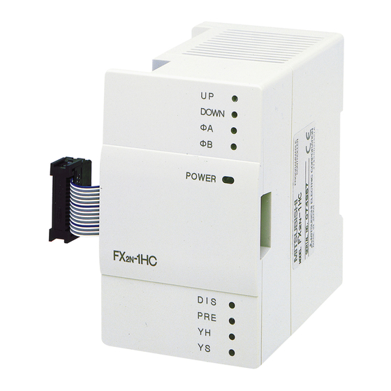
1.1 External dimensions
87(3.43)
1
17
16
Mounting hole 2-φ4.5 (0.18)
1
Extension cable and connector
2
UP LED
3
DN (Down) LED
4
φA LED
5
φB LED
6
POWER LED
7
φA, φB terminal (M3 (0.12) screws)
8
PRESET terminal (M3 (0.12) screws)
9
<Using the solderless termination>
6.2mm
(0.24 inches)
or less
FOR M3
(0.12 inches)
6.2mm
(0.24 inches)
or less
FX
-1HC SPECIAL FUNCTION BLOCK
2N
-1HC counts at a higher speed than the built-in high-
2N
-1HC unit to run only after setting these mode parameters.
2N
-1HC and the FX
PLC is by buffer memory exchange. There are 32
2N
2N
-1HC.
2N
, FX
2N
2NC
Mass (weight): Approx. 0.3 kg (0.66 lbs) Dimensions: mm (inches)
Accessories: Self-adhesive labels special block number identification.
55(2.17)
4(0.16)
2
4 (0.16)
YHxYS terminal (M3 (0.12) screws)
10
DISABLE terminal (M3 (0.12) screws)
11
DIS (DISABLE) LED
12
PRESET LED
13
YH LED
14
YS LED
15
DIN rail clip
16
Attachment groove for 35 (1.38) wide DIN rail
17
•
Use crimp terminals of the dimensions specified in the left figure.
•
Secure the terminals using a tightening torque of 0.5 to 0.8 Nxm
(5 to 8 kgxcm).
•
Wire only to the module terminals discussed in this manual.
Leave all others vacant.
USER'S GUIDE
JY992D65401C
SERIES HARDWARE
2N
expansion bus. The 8 points can be allo-
55(2.17)
3
UP
4
DOWN
ø
5
A
ø
B
6
POWER
7
11
12
DIS
13
PRE
14
YH
YS
15
8
11
9
10
Advertisement
Table of Contents

Related Manuals for Mitsubishi Electric FX2N-1HC


Summary of Contents for Mitsubishi Electric FX2N-1HC
- Page 1 -1HC SPECIAL FUNCTION BLOCK USER’S GUIDE JY992D65401C This manual contains text, diagrams and explanations which will guide the reader in the correct installation and operation of the FX -1HC special function block and should be read and understood before attempting to install or use the unit.
-
Page 2: Specifications
2. WIRING PNP output encoders PNP output encoders 3.3k FX2N-1HC A24+ Shielding Wire 1.5k :source Phase A A12+ 0.27k :sink A5 + ØA 0.1k B24+ 2.2kW Shielding Wire Phase B B12+ B5 + ØB 12 to 24V inputtable Shielding Wire 1.5k... - Page 3 3.3 Buffer memories (BFM) BFM number Contents Counter mode K0 to K11 Default: K0 DOWN/UP command (1-phase 1-input mode) Default: K0 #3,#2 Ring length Upper/Lower Default: K65,536 Write Command Default: K0 #11,#10 Preset data Upper/Lower Default: K0 #13,#12 YH compare value Upper/Lower Default: K32,767 #15,#14 YS compare value Upper/Lower...
- Page 4 2) BFM #3, #2 Ring length Stores the data that specifies the length of the 16-bit counter (default: K65,536). 98 99 X 002 DOWN K100 99 98 In the above example, K100 is written into BFMs #3 and When ring length K100 is specified, the #2 of special block No.2 as a 32-bit binary value (BFM value of the counter changes as shown #3 = 0, BFM #2 = 100).
- Page 5 10) BFM #29 Error status Error status in the FX -1HC can be checked by reading the contents of b0 to b7 of BFM #29 to auxiliary relays of the PLC. BFM#29 Error status Set when any of b1 to b7 is ON. Set when the value of the ring length is written incorrectly (other than K2 to K65,536).
- Page 6 • All examples and diagrams shown in this manual are intended only as an aid to understanding the text, not to guarantee operation. Mitsubishi Electric will accept no responsibility for actual use of the product based on these illustrative examples.
Need help?
Do you have a question about the FX2N-1HC and is the answer not in the manual?
Questions and answers