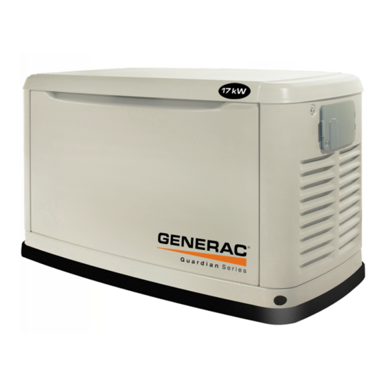
Summary of Contents for Generac Power Systems Guardian Series
- Page 1 The BASIC “How-To” Installation Guide For The Do-It-Yourselfer Emergency Emergency Automatic Automatic Backup Power System Backup Power System www.guardiangenerators.com...
-
Page 2: Read This Manual Thoroughly
Thank you for purchasing this model of the Guardian product line by near the unit’s installation site. Safety should be stressed to Generac Power Systems Inc. This model is a compact, high all operators and potential operators of this equipment. -
Page 3: General Hazards
• After installing this home standby electrical system, the generator GENERAL HAZARDS may crank and start at any time without warning. When this occurs, • For safety reasons, Generac recommends that the installation, load circuits are transferred to the STANDBY (generator) power initial start-up and maintenance of this equipment is carried out source. - Page 4 INSTALLATION SYSTEM EQUIPPED WITH: • External Connection Box with 5’ pre-wired flexible conduit from generator for easy plug’ n play connection to transfer switch. • 1’ flexible fuel line • Composite Mounting Pad • UL listed wire nuts (not shown) •...
- Page 5 PLEASE READ ENTIRE GUIDE BEFORE STARTING THE INSTALLATION PROCESS TO BE AWARE OF ALL REQUIREMENTS. TOOLS REQUIRED: Drill, Drill Bits, Hole Saw (type and length will be determined by the materials you will be drilling and cutting), Open-End Wrenches or Adjustable Wrenches, Socket Wrenches or Nut Drivers, Standard and Phillips Screwdrivers, Level, Sledge Hammer, Channel-lock Pliers, Spade Shovel, and Safety Goggles.
- Page 6 Site Preparation and Generator Placement Crushed Stone or Pea Gravel Clear an feet by 5 feet of grass and FUEL HOOK UP & CHECK FOR LEAKS Make k k the should igid fuel and 6 inches be piping length of pad (48"...
-
Page 7: Connection Box
Threaded Lock Nut Drill Pass Through Hole 11b. Remove the threaded lock nut from the conduit coupling. 10a. CONNECTION TO CONNECTION BOX Deter xible will pass house from . When you are cer Connect Wires Connect Wires have inside the w ill a small pilot hole through the wall to mark the Drill Hole Through House... - Page 8 Install Automatic Transfer Switch Connection of Emergency Circuits 1ft. 12. MOUNTING OF AUTOMATIC TRANSFER SWITCH 13a. CONNECTION OF EMERGENCY CIRCUITS Locate automatic transfer switch with built-in emergency load Remove the main electrical distribution panel cover. Remove center within one foot of main distribution panel. The automatic appropriate size knockout from the bottom or side of the main transfer switch with built-in load center can be located to the panel.
-
Page 9: Test System
Connect positive (+) (red) cable to positive (+) battery post. Connect negative (-) (black) ground cable to negative (-) Install the appropriate Circuit Breaker battery post. UL approved wire nuts are included with installation kit. NOTE: In areas where temperatures regularly fall below NOTE: In areas where temperatures regularly fall below 10°F (-12°C) it is recommended that a pad type battery heater be installed to aid in cold climate starting. - Page 10 ELECTRICAL INSTALLATION DRAWING...
- Page 12 Please read all information prior to installation and operation of your Guardian ® Emergency Automatic Backup Power System. by Generac Power Systems, Inc. GENERAC POWER SYSTEMS, INC. P.O. BOX 297 • WHITEWATER, WISCONSIN 53190 WEBSITE: www.guardiangenerators.com Part# OD8561 Rev. A 2.03...


Need help?
Do you have a question about the Guardian Series and is the answer not in the manual?
Questions and answers