
Related Manuals for Grin Cycle Analyst V3.1

Summary of Contents for Grin Cycle Analyst V3.1
- Page 1 Cycle Analyst V3.1 Official User Manual Grin Technologies Ltd Vancouver, BC, Canada (604) 569-0902 email: info@ebikes.ca web: http://www.ebikes.ca Copyright © 2019...
-
Page 2: Table Of Contents
Cycle Analyst V3.1 User Manual Rev 1.0 Table of Contents 1 Introduction...................3 2 High Level Operation..............3 3 Installation..................4 3.1 Handlebar Wiring..................4 3.2 Shunt / Controller Wiring.................6 4 Display Screens................7 4.1 Main Display....................7 4.2 Diagnostics Screen, Display #12...............8 4.3 Wh/km, Display #4..................9 5 Resetting the Trip Counter............9... -
Page 3: Introduction
Rev 1.0 1 Introduction Thank you for the purchase of a V3 Cycle Analyst device, Grin's latest model of open standard display and control device for ebikes and other electric vehicles. This document should help you get reasonably familiar with the basic setup and operation of a CA3 as part of your vehicle system. -
Page 4: Installation
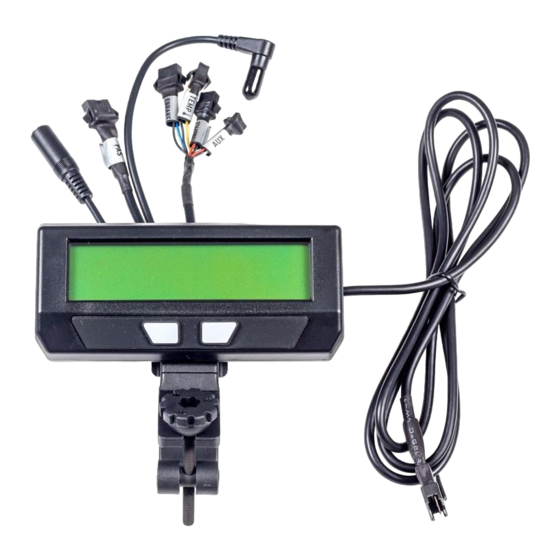
Cycle Analyst V3.1 User Manual Rev 1.0 3 Installation The Cycle Analyst includes a handlebar bracket that allows it to clamp on any tube from 21mm (7/8”) to 40mm (1.5”) in diameter. You can mount it directly on the handlebar, or you can swivel the base 90 degrees and clamp it to the stem for a more central display that doesn’t consume bar real estate. - Page 5 Cycle Analyst V3.1 User Manual Rev 1.0 There are two additional short cables coming out of the Cycle Analyst. One is an 1/8” TRS communications jack that can be used for data logging or connecting to a computer for firmware updates and setting changes. The other is a DC Power cable that has full battery voltage for powering front ebike lights, DC-DC converters, and other peripherals that can run directly off pack voltage.
-
Page 6: Shunt / Controller Wiring
Cycle Analyst V3.1 User Manual Rev 1.0 3.2 Shunt / Controller Wiring For systems that have a CA3 compatible motor controller, the electrical hookup is simply a matter of connecting the 6-pin CA plug to the mating plug on the controller. -
Page 7: Display Screens
Cycle Analyst V3.1 User Manual Rev 1.0 4 Display Screens When the device is powered up you can scroll through numerous display screens by pressing the left and right buttons to show you things of interest Table 1: Summary of CA3.1 Display Screens Display #1, Main Screen Summary of battery level, speed, power, voltage, distance etc. -
Page 8: Diagnostics Screen, Display #12
Cycle Analyst V3.1 User Manual Rev 1.0 charge, during use, and when the battery goes flat. This is often your first clue to anomalous behavior and provides very useful troubleshooting information. The top right is a customizable display field. By default, this toggles between... -
Page 9: Wh/Km, Display #4
Cycle Analyst V3.1 User Manual Rev 1.0 The bottom left shows if any of the limit settings are actively regulating the throttle output voltage. Letters awvst refer to the Amps, Watts, low Voltage, Speed, and Temperature rollbacks, and they become capitalized when active. -
Page 10: Setup Menu
Cycle Analyst V3.1 User Manual Rev 1.0 If you forget to reset, the trip amp-hour, watt-hour, and distance accumulators will eventually peg at their maximum values and you'll stop accumulating new statistics. You also won't get the benefit of seeing an accurate battery charge cycle count, seeing trip to trip variation in your wh/km consumption stats, and learning exactly how many amp-hours the battery is able to deliver. -
Page 11: Setting The Speedometer
Cycle Analyst V3.1 User Manual Rev 1.0 Table 2: CA3.1 Setup Menu Organization Setup Speedometer Configure Speedometer Sensor (wheel diameter, #poles, metric/imperial) Setup Battery Configure Battery Details (chemistry, #cells, low voltage rollback etc) Setup Throttle Input Configure Input Throttle Mapping (min/max range, throttle mode, autocruise) - Page 12 Cycle Analyst V3.1 User Manual Rev 1.0 using the hall sensors for wheel speed, then it will toggle up and down many times as you turn the wheel. Most setup menus provide a preview of the related signals seen by the CA which can be valuable for setup and troubleshooting.
- Page 13 Cycle Analyst V3.1 User Manual Rev 1.0 Table 3: Approximate Tire Circumferences Tire Size Circumf Tire Size Circumf Tire Size Circumf 16 x 1.50 1185 24 x 2.12 1965 26 x 2.25 2115 16 x 1 3/8 1282 26 x 1 1/8 1970 26 x 2.35...
-
Page 14: Setting Up The Battery
Cycle Analyst V3.1 User Manual Rev 1.0 Table 4: #Pole Settings for Common Motor System CA3-DP with Spoke Magnet 1 Pole Bafang Motor, Internal Speedo 6 Poles Crystalyte 400 Series 8 Poles Crystalyte 5000 Series 12 Poles TDCM 5 Spd IGH Hub... - Page 15 Cycle Analyst V3.1 User Manual Rev 1.0 Li-Ion: This is a catch-all lithium ion representative of most 18650 type lithium cells. The majority of ebike lithium packs are best represented by this option LiPo: This represents standard discharge rate ebike grade lithium polymer cells, which show a fairly steady drop in voltage as the battery is drained from 4.2V to 3.0 V/cell.
- Page 16 Cycle Analyst V3.1 User Manual Rev 1.0 6.3.2 Set Your Capacity Here you input the approximate amp-hours of your battery pack in order to help the battery SOC icon remain accurate at tracking changes during high discharge currents. The value does not need to be exact as the battery icon will always gradually readjust itself based on the voltage reading.
-
Page 17: Throttle Input Settings
Cycle Analyst V3.1 User Manual Rev 1.0 6.4 Throttle Input Settings These settings allow you to modify how the throttle input signal coming into the CA3 device is mapped to a throttle output signal going to the motor controller. The default values (pass-thru input of 1.0-4.0V) generally work fine with a broad range of ebike systems using hall effect throttles and there is little need to change them in order to have a working setup. - Page 18 Cycle Analyst V3.1 User Manual Rev 1.0 same power output as if it was full throttle. This is intuitive, although it means that the entire span from no power to maximum power can occur over a small portion of the total throttle motion.
-
Page 19: Output Throttle Settings
Cycle Analyst V3.1 User Manual Rev 1.0 This mode can be useful on long trips when holding fixed throttle level is tedious, but has largely been superceeded by PAS sensors for those wanting throttle-free assistance. 6.5 Output Throttle Settings The throttle output menu contains the configuration details for the signal that the CA3 sends to the motor controller, including the minimum to maximum voltage swing and the maximum rate at which the throttle signal can ramp up or down. -
Page 20: Setup Power Limits
Cycle Analyst V3.1 User Manual Rev 1.0 These features are most often used to make setups comply with local ebike regulations that stipulate maximum speed for motor assistance, and sometimes a different limit when pedaling versus just using the throttle. A 3 term PID control algorithm is employed in firmware to enable a smooth rollback of motor power as target speed is reached without oscillation. -
Page 21: Setting Up Pas Or Torque Sensors
Cycle Analyst V3.1 User Manual Rev 1.0 6.8 Setting Up PAS or Torque Sensors The setup of a PAS sensor involves telling the CA3 details of both the type of PAS device that is connected, as well as how to respond to pedal input. -
Page 22: Pas Configuration
Cycle Analyst V3.1 User Manual Rev 1.0 Without that it will not show an accurate measure of the human power input, nor will it be able to scale the rider's pedal effort into a proportional motor power. Fortunately there are a number of preconfigured torque sensor devices in the CA3.1 setup menu which will preload appropriate default values for that sensor... - Page 23 Cycle Analyst V3.1 User Manual Rev 1.0 In all 3 PAS modes you can control the timing when PAS kicks in as you start pedaling, and how long it lingers after you stop pedaling. This is done by editing the PAS Start and Stop Thresholds.
-
Page 24: Temperature Sensor
The Cycle Analyst has a 2-pin input intended for motor temperature sensing. Many motors supplied by Grin have a 10K NTC thermistor (Beta constant of 3900) prewired into the stator which can hook up to the CA3 through a 2-wire extension cable. -
Page 25: Setup Auxiliary Control Inputs
Cycle Analyst V3.1 User Manual Rev 1.0 6.11 Setup Auxiliary Control Inputs The auxilliary input on the Cycle Analyst allows for the rider to adjust settings on the fly without going into the Cycle Analyst setup menu. This is popular on bikes that have PAS or Torque sensors on them in order to adjust the assist level while riding. - Page 26 Cycle Analyst V3.1 User Manual Rev 1.0 With the Digital Aux input, you can set the number steps as well as the percentage corresponding to the first step in case you want the lowest setting to be above zero. With the Analog Aux input, the adjustment parameters depend on whether the control is a 2 or 3 position switch, or a continuously adjustable potentiometer.
-
Page 27: Setup Ebrakes And Regen
Brake Out voltage, effectively cutting power to the motor. With Grin and certain third party controllers, the throttle signal range from 0.0V to 0.8V is mapped to do proportional regenerative braking. This mapping allows the CA3 to regulate motor braking behavior on the same throttle output signal. -
Page 28: Set Current Sense Shunt Resistance
2-3 mOhm. Ezee controllers are about 1.5 mOhm and the Grin Phaserunner / Baserunner are both 1.0 mOhm. If you leave RShunt at the default value of 1.000 mOhm on controllers that have a higher actual resistance, then the amps and watts readings will be way too high. - Page 29 Cycle Analyst V3.1 User Manual Rev 1.0 High current shunt resistors for larger EV's do not typically list their rating in mOhm. Instead they are characterized by the current which will produce a full scale reading on a 50mV (most common) or 100mV galvanometer. To calculate the RShunt from one of these devices, divide the mV full scale value of the shunt by the amps rating.
-
Page 30: Using Presets
Cycle Analyst V3.1 User Manual Rev 1.0 6.14 Using Presets Mode presets are useful for riders wanting a shortcut to quickly switch between up to three preconfigured groups of power limits, speed limits, and PAS / throttle mode settings. This is commonly used for bike setups with street legal and off- road modes, or to switch between various economy and high power levels. -
Page 31: Display Customization
Cycle Analyst V3.1 User Manual Rev 1.0 6.15 Display Customization The CA3.1 provides many options for customizing the screens to display only information that is pertinent to a given setup and user. Any of the 12 display screens can be hidden from view while in motion or while stopped. Many fields on the main screen can be user set, and it's possible to enable an automatic return to the main display after a short time without needing to navigate home. - Page 32 We do not currently produce any software applications designed for the realtime logging and graphical display of this information, although free terminal programs are available on all platforms to display and log serial data. Grin does produce a product (the Cycle Analogger) that is plug and play with CA devices and conveniently logs data directly to an SD memory card along with optional GPS data.
-
Page 33: Software Setup Utility
Cycle Analyst V3.1 User Manual Rev 1.0 8 Software Setup Utility The Cycle Analyst Setup Utility software is available for Windows, MacOS, and Linux, and it lets you edit all the CA3 parameters by computer rather than through the two button interface. The software also allows you to update and reflash the firmware on the Cycle Analyst, and load various special purpose firmwares like the Solar CA code or GPS code. -
Page 34: Common Mistakes
Hooking up a PAS sensor not able to handle 10V: The power on the 5- pin PAS plug is 10V in order to be compatible with torque sensor models. The Grin supplied PAS sensors have all been modified to handle 10V power, but most third party PAS sensors can't. Hooking them up without adding an inline 5V regulator will typically fry the PAS sensor. -
Page 35: Enjoy Your Ride And Remember To Reset
Cycle Analyst V3.1 User Manual Rev 1.0 10 Enjoy your Ride and Remember to Reset That's it! After 34 pages of study, we hope that this Version 3.1 Cycle Analyst lets you not only achieve the performance behavior you want from your ebike, but that in using it you gain a new level of understanding on how ebike systems in general work and operate. -
Page 36: Specifications
Cycle Analyst V3.1 User Manual Rev 1.0 11 Specifications 11.1.1 Cables and Connectors JST-SM connector series for signal lines. DC Power is 5.5x2.1mm. 11.1.2 Electrical Voltage Range 10-150V, but derated by accessory current draw. With common torque sensors on PAS plug, 60V max.
Need help?
Do you have a question about the Cycle Analyst V3.1 and is the answer not in the manual?
Questions and answers