Table of Contents
Advertisement
Quick Links
PRINTED IN USA
P/N 990-30207
MAINTENANCE MANUAL
OWNER:_______________________________________________________________________
_________________________________________________________________________
_________________________________________________________________________
SOLD AND SERVICED BY:________________________________________________________
MODEL NO. ___________________________SERIAL NO. ______________________________
OPERATION AND
IC-250-3D
___________________________________________________________
___________________________________________________________
COPYRIGHT 2013
BRODERSON MFG. CORP.
LENEXA, KANSAS 66215
Advertisement
Table of Contents

Related Manuals for Broderson IC-250-3D


Summary of Contents for Broderson IC-250-3D
- Page 1 PRINTED IN USA COPYRIGHT 2013 P/N 990-30207 BRODERSON MFG. CORP. LENEXA, KANSAS 66215 OPERATION AND MAINTENANCE MANUAL IC-250-3D OWNER:_______________________________________________________________________ _________________________________________________________________________ _________________________________________________________________________ SOLD AND SERVICED BY:________________________________________________________ ___________________________________________________________ ___________________________________________________________ MODEL NO. ___________________________SERIAL NO. ______________________________...
- Page 2 STATEMENT OF WARRANTY FOR MOBILE CRANES Broderson Manufacturing Corp. ("BMC") warrants its products to be free from defects in material or workmanship at the date of shipment from BMC. This warranty shall be effective only when validated by the return to BMC of it’s standard form of Warranty...
-
Page 3: Table Of Contents
Driving the Vehicle…………………………………………….. 2-10 Operating the Crane………………………………………….. 2-10 Normal Gauge Reading………………………………………. 2-10 Rated Capacity Limiter………………..……………………… 2-11 Crane Capacity…………………...……………..……………………...… 2-12 Crane Capacity Chart IC-250-3D……………………………. 2-14 Capacity Example…………………………………………….. 2-15 Sheave Block and Downhaul Weight……………………………………. 2-16 Two-Part Line Reaving……………………………………………………. 2-17 Four-Part Line Reaving…………………………………………………… 2-17 Safety Devices…………………………………………………………….. - Page 4 SECTION 3 MAINTENANCE Safety Rules……………………………………………………………….. New Unit Inspection and Test……………………………………………. Operator Inspection and Test……………………………………………. Maintenance Checklist……………………………………………………. Fluid Volume…………..……………………………………………………. Lubrication…………………………………………………………………. Lubrication Chart……………………………………………… Lubrication Schedule………………………………………….. 3-10 Boom Chain Lubrication………………………………………. 3-11 Rotation System Lubrication………………………………….. 3-12 Transmission Fluids…………………………………………… 3-12 Axle Lubrication………………………………………………… 3-12 Wire Rope Lubrication………………………………………… 3-13 Hoist Cable Installation and Inspection…………………………………..
-
Page 5: Introduction
IC-250-3D INDUSTRIAL CRANE INTRODUCTION The Broderson IC-250-3D was designed and built to provide safe dependable and efficient crane service. This we warrant by our testing and quality control procedures. To properly utilize the full potential of the equipment, the following customer controlled conditions must exist: The operator must understand the equipment. -
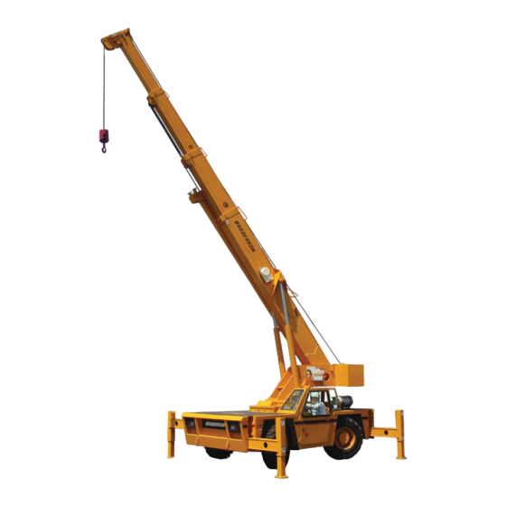
Page 6: Ic-250-3D Dimensions
IC-250-3D DIMENSIONS... -
Page 7: Turning Dimensions
IC-250-3D TURNING DIMENSIONS... -
Page 8: Description And Specification
SECTION 1 DESCRIPTION AND SPECIFICATIONS The IC-250-3D is a self-propelled Industrial Crane designed for material handling and maintenance and repair of equipment, with special features of self-loading cargo decks, 4-wheel steer, and front- wheel drive (4-wheel drive optional). The basic unit consists of a chassis and hydraulic boom assembly. - Page 9 General: (cont’d.) Extension: W/O Boom Extension With Boom Extension Sheave Height (Nominal): 60.7 feet (18.47m) 79.5 feet (24.23m) Horizontal Reach: 50.1 feet (15.27m) 70.1 feet (21.36m) Weight: Total 37,700 pounds (17100kg) Front Axle 17,100 pounds (7800kg) Rear Axle 20,600 pounds (9300kg) Turning Radius: (4-Wheel Steering) 14.3 feet (4.37m) Aisle Width for 90°...
- Page 10 Transmission: Standard 2-Wheel Drive: Powershift transmission with four speeds in forward and reverse. Provides powershifts at any engine speed in any gear. All shifting is done with a single lever electrical control mounted on the steering column. Multiple-disc clutch packs operated by solenoid valves provide reverse, neutral, forward and speed selection.
- Page 11 Brakes: Standard: Split-system, four-wheel hydraulically-boosted multiple-plate wet disc brakes. Uses mineral oil. Hand lever actuated disc-type parking brake on transmission. Tires: Standard 2-Wheel & 4-Wheel Drive: 385/65D22.5, 16-ply, high-traction on/off road tread. Tire Options: Foam Filling of Tires: Foam filling of four IC-250 tires. Net Weight: 2000 pounds (907kg) Non-Marking Pnuematic: 385/65D22.5 16-ply.
- Page 12 Chassis: (cont’d.) Lifting Rings: Consists of four rings, one at each corner of the load deck, so sling can be attached for lifting crane. Rings hang below deck surface when not in use. Chassis Options and Accessories: Auxiliary Winch: Optional worm gear winch, mounted behind front bumper, with a single lever control at the operator's console.
- Page 13 Operator Compartment Options and Accessories: (cont’d.) Cab Heater only: Provides 12,400 BTU heater with two-speed fan for units without All Weather Cab. Net Weight: 12 pounds (5kg) Windshield Washer: Provides reservoir, pump and nozzle for windshield washer Floor Mat: Vinyl mat with foam backing covers floor, front wall and lower portion of right hand wall of operator’s compartment.
- Page 14 Optional Electrical Accessories: Strobe Lights: Two yellow strobe lights, one on each side of turret weight box, for high visibility all around crane. Flashes 60-120 times per minute. Each strobe draws only one-half amp. Includes operator controlled switch. Net Weight: 5 pounds (2kg) Boom Work Lights: Two halogen work lights, one on left side of boom to light boom tip, and one on right side of the turret to light ground under boom tip.
- Page 15 Rated Capacity Limiter: Operational aid that warns operator of impending overload with audible and visual signals. Has read-outs for load, boom angle, boom length and load radius. In the event of an overload, dumps the following boom functions: HOIST RAISE, TELESCOPE EXTEND, BOOM LOWER, SWING LEFT and SWING RIGHT.
-
Page 17: Safety Rules
OPERATION SECTION SAFETY RULES GENERAL: 1. Since the manufacturer has no direct control over machine application and operation, conformance with good safety practice is the responsibility of the user and his operating personnel. 4. The operator shall be responsible for those operations under his direct control. Whenever there is any doubt as to safety, the operator shall have the authority to stop and refuse to handle loads until safety has been assured. - Page 18 3. Keep operator's compartment and decks free of mud and grease. 4. If crane is equipped with a cab, keep all window glass clean. Keep gauges clean. 5. Tools, lubricants, or rags on the crane should be kept in a secured toolbox. 8.
-
Page 19: Lifting
LIFTING: 1. Always refer to Crane Capacity Chart in operator's compartment before handling load. Do not exceed load ratings. Under some conditions the standard capacity ratings cannot be recommended and must be adjusted downward to compensate for special hazards, such as weak supporting ground, wind, hazardous surroundings, operator inexperience, etc. - Page 20 9. Crane may tip at less than rated loads if the surface is uncompacted or wet dirt, or soft soil with frozen crust, thin or cracked pavement, or surface near a hole or ledge. Always use adequate outrigger floats and/or cribbing. See page 2-15. 10.The operator shall not leave the controls while the load is suspended.
- Page 21 CAUTION Keep hands out of Anti-Two-Block mechanism. Serious injury can result from moving parts. 17. Avoid two-blocking. A. Stop raising hoist line before downhaul or hook block strikes boom tip plates. B. Pay out hoist line while extending boom. C. Maintain clearance between downhaul weight or hook block and boom tip while booming down.
- Page 22 22. Crane has four lifting rings, one at each corner of load deck, for lifting the crane. Use proper slings and rigging methods to keep the load balanced during the lift. Do not lift by the boom. Proper lifting and securing practices are the responsibility of the rigger in charge.
-
Page 23: Travel
TRAVEL: 1. For Pick and Carry operation: Traveling with suspended loads involves so many variables, such as ground conditions, boom length and vehicle acceleration, that it is impossible to devise a single standard rating procedure with any assurance of safety. For such operations, the user must evaluate prevailing conditions and determine safe practices using precautions, such as the following: A. -
Page 24: Instruments And Controls
INSTRUMENTS AND CONTROLS The IC-250 instrument panel is equipped with a fuel gauge and warning lights. An hourmeter and a bubble level are also included in the instrument package. Also included are warning lights for low oil and transmission pressure, check engine, high coolant and transmission temperature, hydraulic oil temperature, turn signal, high beam, hazard lights, parking brake and optional four-wheel drive. -
Page 25: Control Functions
CONTROL VALVE FUNCTIONS The controls for operating the outriggers, boom rotation, boom elevation, boom extension and hoist are located along the forward dashboard area. The control handles are directly connected to the 3-position hydraulic valves. The placard located next to these handles identifies the function and direction resulting from each handle movement. -
Page 26: Sequence Of Operation
SEQUENCE OF OPERATION DRIVING THE VEHICLE The following procedure is recommended for driving the vehicle: Perform the daily inspection and test. (See Page 3-4) Apply park brake. Place transmission control lever in neutral. Start engine and allow a warming period. While warming the engine, set up the Rated Capacity Limiter configuration. -
Page 27: Rated Capacity Limiter
W A R N I N G Vapors can be formed inside fuel tank and cause buildup of pressure that can result in sudden expulsion of gasoline and gasoline vapors from the filler neck when the fuel cap is removed from a hot tank. Remove cap slowly. Fuel spray may cause injury. -
Page 28: Crane Capacity
W A R N I N G We recommend the CANCEL button and emergency override switch be used with discretion. Improper or careless use of this switch can cause damage to the crane and endanger people and property. The operator who uses these overrides in an emergency should use good judgment. - Page 29 The Rated Capacity Limiter is designed to stop crane functions at the limitations of the capacity chart. These are: BOOM LOWER, TELESCOPE EXTEND, HOIST RAISE, SWING LEFT and SWING RIGHT. Great care must be exercised when handling a load near capacity or near a two-blocking condition.
- Page 30 2-14...
-
Page 31: Capacity Example
C A U T I O N A capacity load may be carried on the boom, or a capacity load may be carried on the deck, but not at the same time. The total of the percent of deck load and the percent of boom load must not exceed 100%. -
Page 32: Sheave Block And Downhaul Weight
SHEAVE BLOCK AND DOWNHAUL WEIGHT The capacity chart shows the approved hoist rope arrangements. The downhaul weight and sheave blocks supplied by Broderson are specially designed to operate the Anti-Two-Block system. Other blocks or downhauls may bypass this system and create a dangerous condition. - Page 33 MULTI-PART LINE REEVING For loads above 9,000 pounds (4080kg) the sheave block must be used. The four-part-line sheave block can be used for loads up to 36,000 pounds (16330kg). The optional two-part- line sheave block can be used for loads up to 18,000 pounds (8160kg). The wedge socket should be pinned to the wedge socket anchor as shown in the figure.
-
Page 34: Safety Devices
SAFETY DEVICES There are certain safety devices on the IC-250 that are designed to maintain control of a load even though power or hydraulic line failure should occur. The operator should understand the function and operation of these devices so that a continual check on their performance can be made. -
Page 35: Optional Equipment
OPTIONAL EQUIPMENT N O T I C E Use appropriate ladders/steps to gain access to the boom tip and deck to perform this installation. INSTALLING AND STOWING BOOM EXTENSION: Set the outriggers. Raise and extend the boom about 30 feet (9 m) above the ground, paying out load line until hook is just above ground. - Page 36 17. Lay the load line back in the boom tip sheaves and insert both retainer pins & cotters. 18. Replace all of the pins in their lugs for storage and insert their haipin cotters. 19. Install the sheave block on the load line, if desired. 20.
-
Page 37: Capacity Example For Boom Extension
CAPACITY EXAMPLES FOR BOOM EXTENSION The BOOM EXTENSION LOAD RADIUS and BOOM EXTENSION ANGLE capacity charts must both be considered when using the boom extension. The smaller capacity specified by the two charts must be used. Refer to the Capacity Chart on page 2-14 for the following examples: In this first example the boom is elevated to 30°... -
Page 38: Front Auxiliary Winch
FRONT AUXILIARY WINCH: The front auxiliary winch is mounted behind the front bumper and is controlled from the operator compartment. The winch has 115’ (35 m) of 7/16” (11 mm) diameter 6x36 EIP- IWRC wire rope (20,200 pound (91 kn) minimum breaking force) and a 5-ton (4.5 metric ton) hook. -
Page 39: Pintle Hooks
PINTLE HOOKS: Available Pintle Hooks allow the crane to tow other disabled vehicles and trailors, and drag loads. 1. Observe the capacity ratings marked near the hook when towing. 2. Exceeding the capacities can damage the drivetrain. 3. Use slow and smooth motions to avoid shock loads or overrunning loads. Make sure other vehicle is occupied and controlling the vehicle being towed. -
Page 40: Switch And Indicator Symbols
SWITCH AND INDICATOR SYMBOLS ON BMC CRANES The following list shows the symbols used to label switches and indicators on BMC cranes. Most symbols are derived from the ISO 3767-1:1998(E) standard. Not all symbols will be included on your BMC crane. On/Start Windshield washer switch Off/Stop... - Page 41 Tire pressure Engine oil pressure low Lift point Engine coolant fill location Engine coolant Tie-down point temperature high Engine coolant low level Transmission oil fill location mark Engine air filter restriction Transmission oil pressure indicator Transmission oil Engine start temperature Brake fluid fill location Engine idle set Hydraulic oil low-level mark...
-
Page 43: Section 3 Maintenance
MAINTENANCE SAFETY RULES 1. Lower load and boom, shutdown engine, remove key and put it in a safe place. Place warnings on the ignition switch and crane controls to prevent unauthorized starting or movement during maintenance. Disconnect battery when disabling crane. Disconnect battery, RCL and engine electronic module when welding on crane. - Page 44 16. Use a hoist when lifting components that weigh 50 pounds (22 kg) or more. Follow all hoist and rigging safety rules. 17. Do not use lower grade fasteners if replacements are necessary. 18. When reinstalling wiring or plumbing after repairs, be sure that it will not be damaged by rubbing against sharp, rough or hot surfaces or edges.
-
Page 45: New Unit Inspection And Test
MAINTENANCE The Broderson IC-250 Industrial Crane will perform better and longer if a program of inspec- tion, lubrication, adjustment and general preventive maintenance is followed. We recommend the following schedule: NEW UNIT INSPECTION AND TEST The following inspection and test should be made before placing the unit on the job. This will insure that no damage or loss of operating capability occurred during shipment. -
Page 46: Operator Inspection And Test
OPERATOR INSPECTION AND TEST An operator, in the course of normal operation, should make certain observations, inspections and tests to assure that the unit is ready to perform safely. Daily: 1. Check levels of engine oil, coolant and transmission fluid. 2. - Page 47 Weekly: 1. Check tire pressure: 120 PSI (827kPa) 2. Check for loose wheel nuts. (500 foot-pounds (680N-m) torque required.) 3. Check lights and turn signals. 4. Check power steering lines for damage. 5. Check brake lines for damage. 6. Check operation of horn. 7.
-
Page 48: Maintenance Checklist
IC-250 MAINTENANCE CHECKLIST Refer to the component maintenance section of this manual and to the engine operator's man- ual for complete instructions. 50 HOUR INTERVAL: 1. 50 hour lubrication as shown on lube schedule. 2. Inspect wire rope thoroughly. 3. Inspect for physical damage and leaks. 4. - Page 49 500 HOUR OR 6 MONTH INTERVAL: 1. 250 hour maintenance. 2. 50, 250 and 500 hour lubrication. 3. Check antifreeze for protection level and cleanliness. 4. Change hydraulic filter element, if not changed in the last 250 hours and inspect oil from element.
-
Page 50: Fluid Volume
FLUID VOLUME Hydraulic reservoir – 54 gallons (204L) Fuel tank – 30 gallons (113L) Planetary hoist – 2.5 quarts 2.4L) Front auxiliary winch – 2 pints (0.9L) 4x2 & 4x4 Front axle – 5.98 gallons (22.6L) housing, .39 gallons (1.5L) each hub 4x4 Rear axle –... - Page 51 IC-250-3D LUBRICATION CHART...
- Page 52 IC-250-3D LUBRICATION SCHEDULE LUBRICATION INTERVALS ITEM DESCRIPTION 1000 MONTHS NOTES LUBE HOUR HOUR HOUR HOUR Accelerator Pedal 1 Zerk Anti-Two-Block Arm 2 Points - Oilcan Axle Differential Check @50, Change @12 Mo.* Axle Kingpins 4 Zerks Axle Pivot Pin 1 Zerk Axle Hubs Check @50, Change @12 Mo.*...
-
Page 53: Boom Chain Lubrication
BOOM CHAIN LUBRICATION Lubricate inner chains and chain sheaves through windows with boom fully extended and set horizontally. There are grease fittings on chain sheave shafts both inside and outside the boom. Reach in through boom windows with a long tipped oil can and spray chains generously and grease sheave fittings. - Page 54 DRIVE AXLES--HUBS AND DIFFERENTIALS: Maintain lubricant to levels shown here with Mobil 424 or equivalent. Axle factory service man- uals are available from Broderson. Order BMC Part No. 990-00020. *No lubricant is required in the center section of the 2WD rear axle.
-
Page 55: Wire Rope Lubrication
WIRE ROPE LUBRICATION The wire rope should be cleaned and lubricated every 50 hours of normal operation and more frequently when used in dirty or corrosive environments. Whenever the rope is dirty or dry, it should be serviced. The rope should be cleaned with solvent and compressed air or solvent and rags. - Page 56 5. Position the hoist drum with the cable anchor on top. 6. Insert the cable through the anchor slot and wrap it around the anchor wedge. The end of the cable should extend past the wedge by about one inch (24mm). 7.
-
Page 57: Hydraulic System Description
HYDRAULIC SYSTEM The IC-250 hydraulic system consists of two subsystems, driven by a double pump with a single inlet port. The 29 GPM (110L/min) vane pump supplies the hydrostatic steering function and the boom and outrigger functions. The hoist and brake booster are powered by the 34 GPM (129L/min) vane pump. - Page 58 3-16...
- Page 59 3-17...
-
Page 60: Care Of Hydraulic Oil
CARE OF HYDRAULIC OIL The hydraulic system contains many highly pressurized, precision components. To protect the- se, it is very important to keep the hydraulic oil clean, at proper temperature, within the oil specification and to the proper fill level. The IC-250 is equipped with a 100-mesh suction strainer, a breather filter, a 10-micron return- line filter and a 54 gallon tank (204L). - Page 61 HYDRAULIC OILS FOR IC-250 AMBIENT TEMP RANGE: -40° to 75°F -15° to 110°F 50° to 130°F (40° to 24°C) (26° to 43°C) (10° to 54°C) POUR POINT: -40°F MAX -15°F MAX 0°F MAX (-40°C) (-26°C) (-18°C) VISCOSITY INDEX: 140 MIN 95 to 100 95 to 100 VISC.
-
Page 62: Removal Of Air From Hydraulic Circuits
REMOVAL OF AIR FROM HYDRAULIC CIRCUITS To remove air from hydraulic circuits, perform the following steps: 1. Ensure all main shutoff valves on the reservoir are open. 2. Start the engine. 3. Raise and lower the boom minimum five times. Ensure that the cylinder travels full stroke. -
Page 63: Hydraulic Seals
HYDRAULIC SEALS W A R N I N G Do not check for hydraulic leaks with hands. If a mist of hydraulic oil is noticed around a line or component, use cardboard or other material to check for location of leak. High pressure fluid leaking from a small hole, can be almost invisible, yet have enough force to penetrate the skin. -
Page 64: Pressure Settings
PRESSURE SETTINGS: The hydraulic system is divided into two pressure circuits, each having its own protective ad- justable relief valve in the inlet sections of the control valve. The functions operated by the con- trol valve sections require different pressures for different functions. These are shown below: 1. -
Page 65: Boom And Outrigger Circuit
BOOM AND OUTRIGGER CIRCUIT: The relief valve pressure setting at the inlet for boom control sections is 3000 PSI (207bar). This pressure is required for all but the swing control section. Two work port relief valves are installed in the swing section. These relief valves are set at 1500 PSI (103bar). The relief pressure at the inlet end of the valve can be adjusted with a wrench and an allen wrench. -
Page 66: Telescope Cylinder Holding Valves
To determine whether the problem is in the left or right-hand cylinder, put a pressure gauge with a range of at least 5000 PSI (350bar) on the ¼” size port on the side of one of the holding valves. W A R N I N G Disconnecting the RCL hose from a single holding valve may cause the boom to lower if the other holding valve is faulty. -
Page 67: Boom Chain Adjustment
BOOM CHAIN ADJUSTMENT Study Illustrations 1,2 and 3 to understand the chain adjustment procedure. Proper adjustment is critical at time of boom assembly or scheduled maintenance. Initial adjustment: Retract boom completely. The 4 stage extension and retraction chains set the position of the 4 stage relative to the 3 stage. - Page 68 BOOM CHAIN ADJUSTMENT 3-26...
-
Page 69: Engine Maintenance
ENGINE MAINTENANCE: Refer to the engine manual for engine maintenance. AIR CLEANER SERVICE: LP Engine: Clean out the dust cup every 50 hours. Loosen the clamps around the cup and housing and remove the cup. Dump dust out of cup. Clean gasket and sealing surfaces with a damp cloth. Replace cup gasket if it shows signs of damage. -
Page 70: Mechanical Adjustments
MECHANICAL ADJUSTMENTS FASTENERS: All fasteners on the IC-250 should be checked and retightened if required, as a part of the pre- ventive maintenance program. Particular attention should be give to the drive axle mounting bolts, pump mounting bolts, pump drive shaft bolts, rotation bearing bolts, rotation gearbox bolts, and winch bolts. - Page 71 6. Move the park brake lever fractionally downward, just over center, slightly releasing it. Hold park brake lever switch in the off position. 7. Slowly release the foot brake pedal. 8. If the machine has not moved, use maximum engine speed. The machine should not move. 9.
-
Page 72: Torque Data
TORQUE DATA BOLT SAE GRADE SAE GRADE SAE GRADE GRADE 1 OR 2 MARKING MEDIUM CARBON MEDIUM CARBON MATERIAL STEEL ALLOY STEEL LOW CARBON Q & T Q & T MINIMUM TENSILE 64,000 PSI 120,000 PSI 150,000 PSI STRENGTH (441 MPa) (827 MPa) (1034 MPa) BOLT SIZE...
Need help?
Do you have a question about the IC-250-3D and is the answer not in the manual?
Questions and answers