Table of Contents
Advertisement
PRINTED IN USA
P/N 990-30227
MAINTENANCE MANUAL
OWNER:_______________________________________________________________________
_______________________________________________________________________
_______________________________________________________________________
SOLD AND SERVICED BY:________________________________________________________
MODEL NO._________________________ SERIAL NO.
OPERATION AND
IC-40-D
________________________________________________________
________________________________________________________
COPYRIGHT 2017
BRODERSON MFG. CORP.
LENEXA, KANSAS 66215
_____________________________
Advertisement
Table of Contents

Related Manuals for Broderson IC-40-D


Summary of Contents for Broderson IC-40-D
- Page 1 PRINTED IN USA COPYRIGHT 2017 P/N 990-30227 BRODERSON MFG. CORP. LENEXA, KANSAS 66215 OPERATION AND MAINTENANCE MANUAL IC-40-D OWNER:_______________________________________________________________________ _______________________________________________________________________ _______________________________________________________________________ SOLD AND SERVICED BY:________________________________________________________ ________________________________________________________ ________________________________________________________ MODEL NO._________________________ SERIAL NO. _____________________________...
- Page 2 STATEMENT OF WARRANTY FOR MOBILE CRANES Broderson Manufacturing Corp. ("BMC") warrants its products to be free from defects in material or workmanship at the date of shipment from BMC. This warranty shall be effective only when validated by the return to BMC of its standard form of Warranty...
-
Page 3: Table Of Contents
TABLE OF CONTENTS SECTION 1 DESCRIPTION and SPECIFICATIONS Introduction………….………………………………………… 1-1 Dimensions and Orientation IC-40-2D………….………… Turning Dimensions IC-40-2D………….…………………. Description and Specifications………….………………… SECTION 2 OPERATION Safety Rules……………..…………………………………… 2-1 Instruments and Controls…………….……………………… 2-8 Control Functions………….………………………… 2-9 3-Mode-Steering Functions………….……………… 2-9 Sequence of Operation………….………………………… 2-10 Driving the Vehicle………….……….…………………... - Page 4 SECTION 3 MAINTENANCE (continued) Hydraulic System Maintenance…………..………………… 3-18 Transmission Start-Up Procedure………...………. 3-18 Transmission Troubleshooting………….………..… 3-19 Care of Hydraulic Oil………...………..……………… 3-20 Hydraulic Oil Specifications………….……….……… 3-21 Purging the Hydraulic System………….………..… 3-21 Hydraulic Seals………….………...………………… 3-24 Hydraulic System Adjustments………..………………… 3-25 Control Valves………….………...…………………… 3-25 Boom Cylinder Holding Valve………...………….… 3-26 Extension Cylinder Holding Valve………….………...
-
Page 5: Introduction
14741 W. 106th St. Lenexa, Kansas 66215 USA 913-888-0606 NOTICE If this crane becomes involved in an accident, please call Broderson Manufacturing Corp. at 913-888-0606, and ask for the Legal Department or the Service Manager. Also, please notify your Broderson dealer. -
Page 6: Dimensions And Orientation Ic-40-2D
DIMENSIONS AND ORIENTATION IC-40-2D... -
Page 7: Turning Dimensions Ic-40-2D
TURNING DIMENSIONS... -
Page 8: Description And Specifications
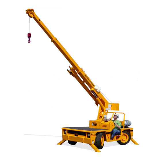
SECTION 1 DESCRIPTION AND SPECIFICATIONS BMC’s IC-40-2D is a self-propelled, industrial crane designed for in-plant lifting and material handling applications. It has the special features of low height, narrow width, short length, cargo deck, four-wheel steer, and four-wheel drive. The basic unit consists of a chassis and a hydraulic boom assembly. - Page 9 Weight Distribution: (Base Machine) Front Axle 4210 pounds (1910 kg) Rear Axle 4710 pounds (2140 kg) Total 8920 pounds (4050 kg) ²) Tire Footprint Area: 40 square inches (260 cm , each ²) Outrigger Footprint Area: 48 square inches (310 cm , each Drawbar Pull: 2000 pounds (910 kg)
- Page 10 Engine: Standard Gasoline: Kubota 1.6L, EFI Dual Fuel, EPA Tier 2 Certified: Kubota WG1605-GL-E3 gasoline engine complete with multi-port electronic fuel injection, dual fuel, and engine management system. Water-cooled, 4-cylinder, 94 CID (1.6 L), 3.11-inch (79 mm) bore, 3.09-inch (78.4 mm) stroke, 57.0 HP (32.6 kW) at governed speed of 2600 rpm.
- Page 11 Brakes: Standard: Primary braking from hydrostatic transmission. Foot-actuated wet-disc brakes in each axle for additional braking in some conditions. Lever-actuated parking brake to hold crane when not being driven. Tires: Standard: 28x9-15 pneumatic tires, 12 PR. Pressurized to 120 PSI (830 kPa) for crane rated loads.
- Page 12 Pintle Hook: T-60-A Holland pintle hook mounted on rear frame member. Rated for 2000 pounds (910 kg) tongue weight. Net Weight: 7 pounds (3 kg) Lifting Sling: Sling to attach to lifting rings. Net Weight: 20 pounds(9 kg) Rear View Mirrors: One right-hand and one left-hand mirror, 6-inch (152 mm) diameter, mounted on deck stakes.
- Page 13 Electrical System: Standard: Electrical Group: 12V DC. Battery: Group 24 with 550 CCA rating. Lighting Group: Consists of 2 headlights and taillights, and a 12V horn activated by button on instrument panel. Display: Located at operator's station and includes fuel gauge, voltmeter, oil pressure, water temperature and hydraulic oil temperature gauges.
- Page 14 Main Hoist: Standard: Turret mounted, planetary gear hoist is hydraulically powered to provide bare- drum line pull of 5000 pounds (2270 kg) and a line speed of 86 ft/min (26 m/min). Main Hoist Rope: Main hoist rope is 3/8” (10 mm) in diameter, Warrington-Seale construction, 6x36 classification, EEIP grade, IWRC core, RRL lay, minimum breaking strength 16,600 lbs (74 kN), 85’...
- Page 15 Optional Boom Attachments: Boom Extension, 8-Foot (2.4 m): Provides 8 feet (2.4 m) of additional length for lifting loads with load line. Boom extension may be stowed along side base boom section when not in use. Tip sheave, attaching brackets, and pins included. Deduct 100 pounds (45 kg) from Capacity Chart when boom extension is in stowed position.
-
Page 17: Safety Rules
OPERATION SECTION SAFETY RULES GENERAL: 1. Since the manufacturer has no direct control over machine application and operation, conformance with good safety practice is the responsibility of the user and his operating personnel. 4. The operator shall be responsible for those operations under his direct control. Whenever there is any doubt as to safety, the operator shall have the authority to stop and refuse to handle loads until safety has been assured. - Page 18 3. Keep operator's compartment and decks free of mud and grease. 4. If crane is equipped with a cab, keep all window glass clean. Keep gauges clean. 5. Tools, lubricants, or rags on the crane should be kept in a secured toolbox. 6.
- Page 19 LIFTING: 1. Always refer to Crane Capacity Chart in operator's compartment before handling load. Do not exceed load ratings. Under some conditions, the standard capacity ratings cannot be recommended and must be adjusted downward to compensate for special hazards. These include: weak supporting ground, wind, hazardous surroundings, operator inexperience, etc.
- Page 20 9. Crane may tip at less than rated loads if the surface is uncompacted or wet dirt, soft soil with frozen crust, thin or cracked pavement, or surface near a hole or ledge. Always use adequate outrigger floats and/or cribbing. See page 2-14. 10.The operator shall not leave the controls while the load is suspended.
- Page 21 CAUTION Keep hands out of Anti-Two-Block mechanism. Serious injury can result from moving parts. 17. Avoid two-blocking. A. Stop raising hoist line before downhaul or hook block strikes boom tip plates. B. Pay out hoist line while extending boom. C. Maintain clearance between downhaul weight or hook block and boom tip while booming down.
- Page 22 22. Crane has four lifting rings, one at each corner of load deck, for lifting the crane. Use proper slings and rigging methods to keep the load balanced during the lift. Do not lift by the boom. Proper lifting and securing practices are the responsibility of the rigger in charge.
- Page 23 TRAVEL: 1. For Pick and Carry operation: Traveling with suspended loads involves so many variables, such as ground conditions, boom length, and vehicle acceleration, that it is impossible to devise a single standard rating procedure with any assurance of safety. For such operations, the user must evaluate prevailing conditions and determine safe practices using precautions, such as the following:...
-
Page 24: Instruments And Controls
OPERATION INSTRUMENTS AND CONTROLS The Broderson IC-40 instrument panel is equipped with a display screen showing electrical system amperage, fuel level, oil pressure, water temperature, hydraulic oil temperature, and engine hours. Also included, is a bubble level, to level the machine. -
Page 25: Control Functions
CONTROL FUNCTIONS The controls for operating the outriggers, boom swing, boom elevation, boom telescope, and hoist are located on the control panel. The handles are directly connected to the four-way hydraulic control valves. The placards adjacent to these handles identify the function controlled and the movement resulting from each handle actuation. -
Page 26: Sequence Of Operation
SEQUENCE OF OPERATION DRIVING THE VEHICLE The following procedure is recommended for driving the vehicle to the job site: Perform the daily inspection and test. (See Page 3-4) Apply park brake. Leave hydrostatic transmission switch in neutral. Start engine and allow a warming period. (If equipped with Safety Shutdown System, depress reset button while starting, and for a few seconds after.) Set up the Rated Capacity Limiter configuration while warming the engine. -
Page 27: Operating The Crane
D A N G E R Like other mobile cranes, the IC-40 will tip over more readily than some types of vehicles. The operator should always control the vehicle speed to be compatible with terrain or road conditions. OPERATING THE CRANE The following procedure is recommended for placing the crane in operation: 1. -
Page 28: Rated Capacity Limiter
RATED CAPACITY LIMITER (RCL) A Rated Capacity Limiter is installed on the crane to assist the operator in estimating loads and measuring load radii. Please read the RCL Operation Manual for complete instructions on operation of the system. Following, are some additional operating tips. Always be aware that the RCL can stop boom movement at capacity load conditions and in two-blocking conditions. -
Page 29: Crane Capacity
CRANE CAPACITY Before lifting loads, the operator must read the Crane Capacity Chart and adhere to the load capacities and radii of handling given. The information provided on this chart is based on stability, structural strength, and hydraulic capacity. To operate the crane safely, the operator must know the weight of the load and handling devices, and the radius of the lifting operation. -
Page 30: Crane Capacity Chart Definitions And Rules
CRANE CAPACITY CHART DEFINITIONS AND RULES: The load radius is the horizontal distance from the centerline of boom rotation (the center of the turntable when it is level), to the vertical load line, with the load suspended. Because of deflections of the boom and carrier, the load radius increases when a load is hoisted from its resting place. - Page 31 C A U T I O N The capacities of this crane are based on all outriggers being FULLY EXTENDED to a firm, level surface. The crane may tip at less than capacity loads if operated in the following manner: Outriggers only partially extended and resting on curbing, shoring, etc.
-
Page 32: Crane Capacity Chart Ic-40-2D
CRANE CAPACITY CHART FOR IC-40-2D 2-16... -
Page 33: Crane Capacity Chart Ic-40-2D Metric
CRANE CAPACITY CHART FOR IC-40-2D METRIC 2-17... -
Page 34: Sheave Block And Downhaul
SHEAVE BLOCK AND DOWNHAUL WEIGHT The capacity chart shows the approved hoist rope arrangements. The downhaul weight and sheave blocks supplied by Broderson are specially designed to operate the anti-two-block system. Other blocks or downhauls may bypass this system and create a dangerous condition. -
Page 35: Two-Part-Line Reeving
TWO-PART LINE REEVING For loads above 4500 pounds (2040 kg), the sheave block must be used. The wedge socket should be pinned to the boom sheave plates, as shown in the figure. The dead end of the rope in the wedge socket should be clamped, as shown in the figure. The clamp must not be used on the live part of the rope. -
Page 36: Safety Devices
SAFETY DEVICES There are safety devices on the IC-40 to maintain control of a load in case of power or hydraulic line failure, or human error. The operator should understand the function and operation of these devices so that a continual check on their performance can be made. OUTRIGGER CYLINDER CHECK VALVE: A double-acting check valve is flange-mounted on each of the outrigger cylinders. -
Page 37: Optional Equipment Operation
OPTIONAL EQUIPMENT INSTALLING BOOM EXTENSION ON TIP OF BOOM: Set the outriggers. Raise and extend boom 20 feet (6 m) above the ground, paying out load line until hook is just above ground. Position boom over front, lower and retract boom leaving the load line on the ground. If the sheave block is installed, remove it. -
Page 38: Boom Extension
SETTING THE OFFSET ANGLE ON THE OFFSETTABLE BOOM EXTENSION: 1. The boom extension must be installed on the main boom tip & the load line, downhaul weight & wedge socket installed on the boom extension, and secured with all of the retainer pins. -
Page 39: Capacity Example For Boom Extension
W A R N I N G The front winch is not designed for lifting personnel or loads. Observe the following safety rules: Never lift or carry personnel with the winch and wire rope. Do not allow anyone to stand near or under the load being moved. Be sure the cable is securely anchored in the drum and that at least 5 wraps of rope remain on the drum to ensure against the rope pulling out of its anchor. -
Page 40: Pintle Hooks
PINTLE HOOKS: Available Pintle Hooks allow the crane to tow other disabled vehicles and trailers, and drag loads. Limit the vertical load to about 1000 pounds (450 kg) and the horizontal pull to about 5000 pounds (2270 kg). Exceeding the capacities can damage the drive train. Use slow and smooth motions to avoid shock loads or overrunning loads. - Page 41 SWITCH AND INDICATOR SYMBOLS ON BMC CRANES The following list shows the symbols used to label switches and indicators on BMC cranes. Most symbols are derived from the ISO 3767-1:1998(E) standard. Not all symbols will be included on your BMC crane. On/Start Windshield washer switch Off/Stop...
- Page 42 Tire pressure Engine oil pressure low Lift point Engine coolant fill location Engine coolant Tie-down point temperature high Engine coolant low level Transmission oil fill location mark Engine air filter restriction Transmission oil pressure indicator Transmission oil Engine start temperature Brake fluid fill location Engine idle set Hydraulic oil low-level mark...
-
Page 43: Maintenance Safety Rules
MAINTENANCE SAFETY RULES Lower load and boom, shutdown engine, remove key, and put it in a safe place. Place warnings on the ignition switch and crane controls to prevent unauthorized starting or movement during maintenance. Disconnect battery when disabling crane. Disconnect battery, RCL, and engine electronic module (gas engine only) when welding on crane. - Page 44 If it is necessary to work on the boom or outriggers in an unstowed condition, block them to prevent them from dropping unexpectedly. Use a hoist when lifting components that weigh 50 pounds (23 kg) or more. Follow all hoist and rigging safety rules. Do not use lower grade fasteners if replacements are necessary.
- Page 45 MAINTENANCE The Broderson IC-40 Industrial Crane will perform better and longer if a program of inspection, lubrication, adjustment, and general preventive maintenance is followed. We recommend the following schedule: NEW UNIT INSPECTION AND TEST The following inspection and test should be made before placing the unit on the job. This will ensure that no damage or loss of operating capability occurred during shipment.
- Page 46 OPERATOR INSPECTION AND TEST An operator, in the course of normal operation, should make certain observations, inspections, and tests to assure that the unit is ready and able to perform safely. Daily: Check radiator coolant level. 2. Check engine oil level. 3.
-
Page 47: Ic-40 Maintenance Checklist
IC-40 MAINTENANCE CHECKLIST Refer to the component maintenance section of this manual and to the engine operator's manual for complete instructions. 50-HOUR INTERVAL: 1. 50-hour lubrication as shown on lube schedule. 2. Inspect wire rope thoroughly. 3. Inspect for physical damage and leaks. 4. - Page 48 1000-HOUR INTERVAL: 1. 50, 250, and 500-hour maintenance. 2. 50, 250, 500, and 1000-hour lubrication. 3. Adjust engine valve clearance per Engine Manual. 4. Check and adjust engine speed per Engine Manual. 5. Perform engine maintenance specified in Engine Manual. 6.
-
Page 49: Lubrication
ROTATION BEARING LUBRICATION There is one grease zerk in a hole on the right-hand side of the turntable base plate. This should be used to lubricate the bearing every 50 hours. Rotate the turntable about 45º and pump some grease into the zerk. Repeat until the turntable has rotated two revolutions. - Page 50 IC-40 LUBRICATION CHART...
-
Page 51: Wire Rope
IC-40 LUBRICATION SCHEDULE LUBRICATION INTERVALS ITEM DESCRIPTION 1000 MONTHS NOTES LUBE HOUR HOUR HOUR HOUR Accelerator Linkage 2 Points (Not on E.F.I.) Anti-Two-Block Arm 2 Points Axle Differential Check @50, Change @12 Mo.* Axle Kingpins 8 Zerks Axle Pivot Pin 2 Zerks Axle Planetary Hubs Check @50, Change @12 Mo.*... -
Page 52: Hoist Cable Installation And Inspection
HOIST CABLE INSTALLATION AND INSPECTION The following steps will assure that the wire rope winds smoothly and evenly on the hoist, and will yield greater safety and longer cable life. Refer to Section 1 of this manual for complete replacement rope specifications. 1. - Page 53 Slowly rotate the hoist while applying tension on the cable in front of the boom. Wear heavy leather gloves and wrap rags around the cable to wipe off any dirt from the cable. Keep hands away from the sheaves and hoist drum while the cable is moving.
-
Page 54: Jic Schematic
JIC SCHEMATIC 3-12... -
Page 55: Jic Schematic Metric
JIC SCHEMATIC METRIC 3-13... -
Page 56: Steering System
HYDRAULIC SYSTEM The IC-40 hydraulic system consists of 3 sub-systems, driven by a triple pump. The 36- GPM (136 L/min) piston pump powers the propulsion system. The 6-GPM (23 L/min) gear pump supplies the hydrostatic steering function, and the boom & outrigger functions. The hoist and optional front winch are powered by the 18-GPM (68 L/min) pump. - Page 57 STEERING SYSTEM 3-15...
- Page 58 PROPULSION SYSTEM The propulsion system is a closed-loop hydrostatic transmission. The variable volume piston pump is driveline driven from the engine crankshaft. The pump can deliver up to 34 GPM (129 L/min) or 4000 PSI (276 bar) to the wheel drive motors. The flow from the wheel drive motors returns directly to the pump inlet, not the reservoir.
-
Page 59: Ic-40 Propulsion System
IC-40 PROPULSION SYSTEM 3-17... - Page 60 START-UP PROCEDURE -- PISTON PUMP When initially starting a new or rebuilt transmission pump, it is extremely important that the start-up procedure be followed. It prevents damaging the unit that might occur if the system is not properly purged and charged with oil before start-up. 1.
- Page 61 6. After the system shows signs of filling, run it in neutral and low idle for 5 minutes. Then extend the outriggers so that drive wheels can spin freely. Reconnect the brake release valve if disconnected in step 3. Place the control switch in the FORWARD position and slowly push the accelerator until the wheels turn slowly.
-
Page 62: Care Of Hydraulic Oil
CARE OF HYDRAULIC OIL The hydraulic system contains many highly pressurized, precision components. protect these, it is very important to keep the hydraulic oil clean, at proper temperature, within the oil specification, and to the proper fill level. The IC-40 is equipped with a 100-mesh suction strainer, a 10-micron suction filter, a breather filter, a 10-micron return-line filter, and a 14-gallon (53 L) tank. -
Page 63: Purging The Hydraulic System
APPROVED HYDRAULIC FLUIDS WARM CLIMATE: COOL CLIMATE: *D-A AUTOTRANS SUPER PLUS MOBIL MULTI-VEHICLE A.T.F MOBIL MULTI-VEHICLE A.T.F. DEXRON VI DEXRON VI * D-A Lube, Autotrans Super Plus, was used at the factory to fill the hydraulic system of your IC-40. C A U T I O N Never add kerosene or other "thinners"... - Page 64 Clean the reservoir & strainer and replace the filter elements & hoses, except the return hose at the inlet of the smaller filter, and the case drain hose at the hydro- static pump. Attach a ¾-inch I.D. return hose at the hydrostatic pump case drain port, and run it into a waste oil sump or barrel.
- Page 65 Position the crane so that the boom may later be fully topped up, rotated, and extended. Do not operate these functions until the proper step. Close the small gate valve in the return line and disconnect the return hose from the return filter inlet again.
-
Page 66: Hydraulic Seals
HYDRAULIC SEALS W A R N I N G Do not check for hydraulic leaks with hands. If a mist of hydraulic oil is noticed around a line or component, use cardboard or other material to check for location of leak. High pressure fluid leaking from a small hole can be almost invisible, yet have enough force to penetrate the skin. - Page 67 CONTROL VALVE ADJUSTMENTS The crane control valve has two relief valves to protect the hydraulic components. The relief valves are adjustable and should be checked and set as follows: 1. Boom and outrigger circuits -- 2600 PSI (179 bar) at full flow. 2.
-
Page 68: Boom Cylinder Holding Valve
BOOM CYLINDER HOLDING VALVE A holding valve is built into the base of the boom lift cylinder barrel. This valve is designed to hold the boom in position should loss of power or pressure line failure occur. To check the boom lift cylinder holding valve, set the outriggers, place the boom in the horizontal position over the front of the crane, and raise rated load about one foot above the ground, using the boom lift cylinder (not the hoist). -
Page 69: Air Cleaner Service
AIR CLEANER SERVICE: Clean out the dust cup every 50 hours. Loosen the clamps around the cup & housing, and remove the cup. Dump dust out of cup. Clean gasket and sealing surfaces with a damp cloth. Replace cup gasket if it shows signs of damage. Replace cup with arrows pointing up and tighten clamp. -
Page 70: Mechanical Adjustments
MECHANICAL ADJUSTMENTS FASTENERS: All fasteners in the IC-40 should be checked and retightened, if required, as a part of the preventive maintenance program. Particular attention should be given to the axle, wheel & hub mounting bolts, pump mounting bolts, rotation bearing bolts, rotation gearbox bolts, and hoist bolts. -
Page 71: Torque Data
TORQUE DATA BOLT SAE GRADE SAE GRADE SAE GRADE GRADE 1 OR 2 MARKING MEDIUM CARBON MEDIUM CARBON MATERIAL LOW CARBON STEEL ALLOY STEEL Q & T Q & T MINIMUM TENSILE 64,000 PSI 120,000 PSI 150,000 PSI STRENGTH (441 MPa) (827 MPa) (1034 MPa) BOLT SIZE...
Need help?
Do you have a question about the IC-40-D and is the answer not in the manual?
Questions and answers