Table of Contents
Advertisement
PRINTED IN USA
P/N 990-30255
M AINTENANCE M ANUAL
OWNER:
_________________________________________ _____________________________
______________________________________________________________________
_________________________________________ _____________________________
SOLD AND SERVICED BY:
M ODEL NO. ___________________________
OPERATION AND
IC-80-3L 4X2
___________________________ ____________________________
_______________________________________________________
_______________________________________________________
SERIAL NO.
COPYRIGHT 2019
BRODERSON M FG. CORP.
LENEXA, KANSAS 66215
_____________________________
Courtesy of CraneMarket.com
Advertisement
Table of Contents

Related Manuals for Broderson IC-80-3L 4X2


Summary of Contents for Broderson IC-80-3L 4X2
- Page 1 PRINTED IN USA COPYRIGHT 2019 P/N 990-30255 BRODERSON M FG. CORP. LENEXA, KANSAS 66215 OPERATION AND M AINTENANCE M ANUAL IC-80-3L 4X2 OWNER: _________________________________________ _____________________________ ______________________________________________________________________ _________________________________________ _____________________________ SOLD AND SERVICED BY: ___________________________ ____________________________ _______________________________________________________ _______________________________________________________ M ODEL NO. ___________________________ SERIAL NO.
- Page 2 STATEMENT OF WARRANTY FOR MOBILE CRANES Broderson Manufacturing Corp. ("BMC") warrants its products to be free from defects in material or workmanship at the date of shipment from BMC. This warranty shall be effective only when validated by the return to BMC of its standard form of Warranty...
-
Page 3: Table Of Contents
TABLE OF CONTENTS SECTION 1 DESCRIPTION and SPECIFICATIONS Introduction………………………………………….………. 1-1 IC-80-3L Dimensions………..……………………………… 1-2 Turning Dimensions……………..…………………………… 1-5 Description and Specifications……..……………………… 1-6 SECTION 2 OPERATION Safety Rules………………………………………………. Instruments and Controls……………………………….. Control Functions…………….………...…………… 2-10 Three-Mode Steer Operations………..……………… 2-10 Sequence of Operation………………………………….. 2-11 Driving the Vehicle…………………...……………… 2-11 Operating the Crane……………….…………………... - Page 4 SECTION 3 MAINTENANCE (continued) Hoist Cable Installation and Inspection………..………… 3-10 Hydraulic System Description…………………...………… 3-12 Steering System……………………………………... 3-12 JIC Schematic………………………………..……… 3-13 JIC Schematic Metric……………………………….. 3-14 Hydraulic System Maintenance…………………...………. 3-15 Care of Hydraulic Oil……………………………….… 3-15 Hydraulic Oil Specifications………………………… 3-16 Hydraulic Seals……………………………………… 3-17 Hydraulic System Adjustments……………...……………..
-
Page 5: Introduction
14741 W. 106 Street Lenexa, Kansas 66215 USA 913-888-0606 NOTICE If this crane becomes involved in an accident, please call Broderson Manufacturing Corp at 913-888-0606, and ask for the Service Manager. Also, please notify your Broderson dealer. Courtesy of CraneMarket.com... - Page 6 IC-80-1L DIMENSIONS Courtesy of CraneMarket.com...
- Page 7 IC-80-2L DIMENSIONS Courtesy of CraneMarket.com...
-
Page 8: Ic-80-3L Dimensions
IC-80-3L DIMENSIONS Courtesy of CraneMarket.com... -
Page 9: Turning Dimensions
IC-80-L TURNING DIMENSIONS Courtesy of CraneMarket.com... -
Page 10: Description And Specifications
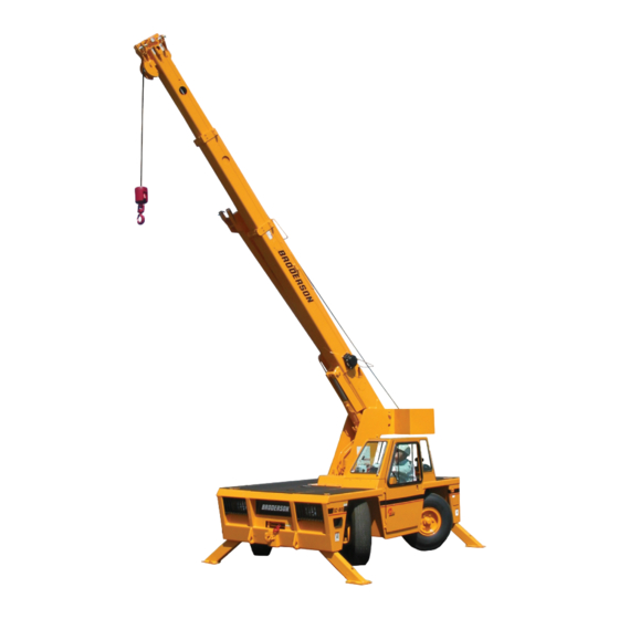
DESCRIPTION AND SPECIFICATIONS The IC-80-L is a self-propelled Industrial Crane designed for in-plant lifting and material handling applications, with special features of low height, narrow width, short length, cargo deck, and standard four-wheel steer and front-wheel drive. The chassis includes a frame, four independently controlled hydraulic outriggers, engine, torque converter, 4-speed powershift transmission, front planetary drive/steer and rear steer axles, fuel tank, hydraulic tank, control station, and full power steering. - Page 11 General Continued: IC-80-1L IC-80-2L IC-80-3L Boom Movement: Rotation Continuous Continuous Continuous Elevation 0° to 70° 0° to 70° 0° to 70° Telescope 12 feet Hyd. 14.5 feet Hyd. 18.5 feet Hyd. (3.66 m) (4.42 m) (5.64 m) Boom Speeds: Rotation 2 RPM 2 RPM 2 RPM...
- Page 12 Engine: Standard Gasoline: GM 3.0L EPA Tier II w/ Dual Fuel: GM Model 3.0L industrial gasoline engine with multi-port electronic fuel injection, dual fuel, catalytic converter, and engine management system. Water cooled, 4-cylinder, 181 CID (3.0 L), bore 4.00 inches (102 mm), stroke 3.60 inches (91 mm), 59 HP (44 kW) at governed speed of 2500 RPM.
- Page 13 4X2 GAS 4X2 DIESEL Travel Drawbar Travel Drawbar Speed Pull Speed Pull Gear Ratios (km/h) (kg) (km/h) (kg) 5.72/1 9500 10500 (4300) (4800) 3.23/1 5500 6000 (11) (2500) (11) (2700) 1.77/1 3000 3500 (19) (1300) (21) (1600) 1.00/1 1800 2000 (31) (800) (34)
- Page 14 Tire Options: Solid Rubber Tires: 8.25 x 15. These tires will reduce overall height and ground clearance by 1½ inches. Net Weight: 400 pounds (181 kg) Foam Filling of Tires: 10.00 x 15, All four tires foam-filled. Net Weight: 900 pounds (408 kg) Spare Tire and Wheel Mounted: Highway Tread, 10.00 x 15, 16-ply, Radial: Net weight: 163 pounds (74 kg)
- Page 15 Outriggers: Four hydraulic outriggers of box-beam construction. Independent controls for each outrigger. Hydraulic cylinders are equipped with direct-connected holding valves. Pad dimensions: 9 inches (23 cm) x 12 inches (30 cm) Pulling Eyes: Heavy eyes on front bumper provided for attachment of hook block so main hoist line can be used for pulling loads at or near floor level.
- Page 16 Operator's Compartment: Standard: Operator’s control station provides one-position access to all operating functions. Includes adjustable operator's seat and retracting seat belt, fire extinguisher, and bubble level. Drum Rotation Indicator: Provides tactile feedback to operator when hoist drum is rotating. Feedback device attached to hoist control handle.
- Page 17 Electrical System: Standard: 12-Volt Battery: Gas Units: Group 27 with 540 CCA rating Diesel Units: Group 31 with 950 CCA rating Instrument Group: Located at operator's station and includes fuel gauge, hourmeter, and bubble level. Hourmeter records hours only during actual engine operation. Also included are: warning lights for low oil and transmission pressure, turn signal, high beams, hazard lights, parking brake, hydraulic oil temperature, battery, check engine, stop engine, coolant temperature, engine oil...
- Page 18 Hydraulic System: Standard: Tandem pump, direct-driven by engine crankshaft, delivers 16 GPM (61 L/min) at 2600 PSI (179 bar) and 32 GPM (121 L/min) at 2500 PSI (172 bar) at 2500 RPM governed engine speed. System protected by relief valves, suction line strainer, and 10-micron full-flow return line filter.
- Page 19 Rated Capacity Limiter: Operator's aid that warns operator of impending overload with audible and visual signals. Has read-outs for load, boom angle, boom length and load radius. In the event of an overload, dumps the following boom functions: HOIST RAISE, TELESCOPE EXTEND, BOOM LOWER, SWING LEFT and SWING RIGHT.
- Page 20 Courtesy of CraneMarket.com...
-
Page 21: Safety Rules
OPERATION SECTION SAFETY RULES GENERAL: 1. Since the manufacturer has no direct control over machine application and operation, conformance with good safety practice is the responsibility of the user and his operating personnel. 4. The operator shall be responsible for those operations under his direct control. Whenever there is any doubt regarding safety, the operator shall have the authority to stop and refuse to handle loads until safety is assured. - Page 22 3. Keep operator's compartment and decks free of mud and grease. 4. If crane is equipped with a cab, keep all window glass clean. Keep gauges clean. 5. Tools, lubricants, or rags on the crane should be kept in a secured toolbox. 8.
- Page 23 LIFTING: 1. Always refer to Crane Capacity Chart in operator's compartment before handling load. Do not exceed load ratings. Under some conditions, the standard capacity ratings cannot be recommended and must be adjusted downward. This compensates for special hazards, such as: weak supporting ground, wind, hazardous surroundings, operator inexperience, etc.
- Page 24 9. Crane may tip at less than rated loads if the surface is uncompacted, has wet dirt, bears soft soil with frozen crust, has thin or cracked pavement, or a surface near a hole or ledge. Always use adequate outrigger floats and/or cribbing. See page 2-14. 10.The operator shall not leave the controls while the load is suspended.
- Page 25 CAUTION Keep hands out of Anti-Two-Block mechanism. Serious injury can result from moving parts. 17. Avoid two-blocking. A. Stop raising hoist line before downhaul or hook block strikes boom tip plates. B. Pay out hoist line while extending boom. C. Maintain clearance between downhaul weight, or hook block and boom tip, while booming down.
- Page 26 22. Crane has four lifting rings, one at each corner of load deck, for lifting the crane. Use proper slings and rigging methods to keep the load balanced during the lift. Do not lift by the boom. Proper lifting and securing practices are the responsibility of the rigger in charge.
- Page 27 TRAVEL: 1. For Pick and Carry operation: Traveling with suspended loads involves so many variables, such as ground conditions, boom length, and vehicle acceleration, that it is impossible to devise a single standard rating procedure with any assurance of safety. For such operations, the user must evaluate prevailing conditions and determine safe practices using precautions, such as the following: A.
-
Page 28: Instruments And Controls
8. Shut off engine before refueling, and remove fuel cap slowly. Vapor pressure in tank can cause a burst of fuel and vapor when the cap is removed. Aways refuel with proper fuel and into proper tank. 9. Know your visibility limitations. Loads being carried on the deck or hanging on the hook can add further limitations to visibility during travel. - Page 29 Normal engine speed-control uses the foot accelerator pedal. On gas engines, only a 3- position switch on the right dash panel provides pre-set engine speeds. Parking brake must be set to activate system. Press the high idle control switch temporarily to the right; the engine will lock into the preset levels.
-
Page 30: Control Functions
CONTROL VALVE FUNCTIONS The controls for operating the outriggers, boom rotation, boom elevation, boom extension and hoist are located along the forward dashboard area. The control handles are directly connected to the 3-position hydraulic valves. The placard located next to these handles identifies the function and direction resulting from each handle movement. -
Page 31: Sequence Of Operation
SEQUENCE OF OPERATION DRIVING THE VEHICLE The following procedure is recommended for driving the vehicle: 1. Perform the daily inspection and test. (See Page 3-4) 2. Apply park brake. 3. Place transmission control lever in NEUTRAL. 4. Start engine and allow a warming period. 5. -
Page 32: Operating The Crane
OPERATING THE CRANE The following procedure is recommended for placing the crane in operation: 1. Perform daily inspection and test. (See Page 3-4) 2. Apply park brake. 3. Place transmission control lever in NEUTRAL. 4. Start engine and allow a warming period at low RPM. 5. -
Page 33: Rated Capacity Limiter
RATED CAPACITY LIMITER (RCL) A Rated Capacity Limiter is installed on the crane to assist the operator in estimating loads and measuring load radii. Please read the RCL Operation Manual for complete instructions on operation of the system. Following, are some additional operating tips. Always be aware that the RCL can stop boom movement at capacity load conditions and in two-blocking conditions. -
Page 34: Crane Capacity
CRANE CAPACITY Before lifting loads, the operator must read the Crane Capacity Chart and adhere to the load capacities and radii of handling given. The information provided on this chart is based on stability, structural strength, and hydraulic capacity. To operate the crane safely, the operator must know the weight of the load and handling devices and the radius of the lifting operation. - Page 35 W A R N I N G The Rated Capacity Limiter can suddenly stop the boom lower and swing functions, causing the load to bounce or swing. Use great care when handling a load near capacity limits or near a two-blocking condition. CRANE CAPACITY CHART DEFINITIONS AND RULES: The load radius is the horizontal distance from the centerline of boom rotation (the center of the turntable when it is level), to the vertical load line with the load suspended.
- Page 36 2-16 Courtesy of CraneMarket.com...
- Page 37 2-17 Courtesy of CraneMarket.com...
- Page 38 2-18 Courtesy of CraneMarket.com...
-
Page 39: Capacity Example
C A U T I O N A capacity load may be carried on the boom, or a capacity load may be carried on the deck, but not at the same time. The total of the percent of deck load and the percent of boom load must not exceed 100%. -
Page 40: Sheave Block And Downhaul Weight
SHEAVE BLOCK AND DOWNHAUL WEIGHT The capacity chart shows the approved hoist rope arrangements. The downhaul weight and sheave blocks supplied by Broderson are specially designed to operate the Anti-Two- Block system. Other blocks or downhauls may bypass this system and create a dangerous condition. -
Page 41: Two-Part-Line Reeving
TWO-PART LINE REEVING For loads above 9000 pounds (4080 kg), the sheave block must be used. The wedge socket should be pinned to the two-part-line lug, as shown in the figure. The dead end of the rope in the wedge socket should be clamped, as shown in the figure. The clamp must not be used on the live part of the rope. -
Page 42: Safety Devices
SAFETY DEVICES There are certain safety devices on the IC-80 that are designed to maintain control of a load if power or hydraulic line failure should occur. The operator should understand the function and operation of these devices so that a continual check on their performance can be made. -
Page 43: Optional Equipment Operation
OPTIONAL EQUIPMENT INSTALLING BOOM EXTENSION ON TIP OF BOOM: Set the outriggers. Raise and extend boom 30 feet (9 m) above the ground, paying out load line until hook is just above ground. Position boom over front, lower and retract boom, leaving the load line on the ground. If the sheave block is installed, remove it. - Page 44 SETTING THE OFFSET ANGLE ON THE OFFSETTABLE BOOM EXTENSION: 1. The boom extension must be installed on the main boom tip and the load line, downhaul weight and wedge socket installed on the boom extension, and secured with all of the retainer pins.
-
Page 45: Capacity Examples For Boom Extension
CAPACITY EXAMPLES FOR BOOM EXTENSION The MAIN BOOM and BOOM EXTENSION capacity charts must both be considered when using the boom extension. The smaller capacity specified by the two charts must be used. Refer to the IC-80-3L Capacity Chart on page 2-17 for the following examples: In this first example the boom is elevated to 30°... -
Page 46: Front Auxiliary Winch
FRONT AUXILIARY WINCH: The front auxiliary winch is mounted behind the front bumper and is controlled from the operator compartment. The winch, with 75 feet (23 m) of 3/8-inch (9.5 mm) diameter 6X36- IWRC-EIP wire rope (15,100-pound (67 kN) breaking strength) and 3-ton (2700 kg) hook, has a single-part-line capacity of 5000 pounds (2270 kg) on the first wrap. -
Page 47: Pintle Hooks
PINTLE HOOKS: Available Pintle Hooks allow the crane to tow other disabled vehicles and trailers, and drag loads. Observe the capacity ratings marked near the hook when towing. Exceeding the capacities can damage the drivetrain. Use slow and smooth motions to avoid shock loads or overrunning loads. Make sure other vehicle is occupied and controlling the vehicle being towed. -
Page 48: Switch And Indicator Symbols
SWITCH AND INDICATOR SYMBOLS ON BMC CRANES The following list shows the symbols used to label switches and indicators on BMC cranes. Most symbols are derived from the ISO 3767-1:1998(E) standard. Not all symbols will be included on your BMC crane. On/Start Windshield washer switch Off/Stop... - Page 49 Tire pressure Engine oil pressure low Lift point Engine coolant fill location Engine coolant Tie-down point temperature high Engine coolant low level Transmission oil fill location mark Engine air filter restriction Transmission oil pressure indicator Transmission oil Engine start temperature Brake fluid fill location Engine idle set Hydraulic oil low-level mark...
-
Page 50: Maintenance
MAINTENANCE SAFETY RULES 1. Lower load and boom, shut down engine, remove key, and put it in a safe place. Place warnings on the ignition switch and crane controls to prevent unauthorized starting or movement during maintenance. Disconnect battery when disabling crane. Disconnect battery, RCL, and engine electronic module (gas engine only) when welding on crane. - Page 51 15. If it is necessary to work on the boom or outriggers in an un-stowed condition, block them to prevent them from dropping unexpectedly. 16. Use a hoist when lifting components that weigh 50 pounds (22 kg) or more. Follow all hoist and rigging safety rules.
- Page 52 MAINTENANCE The Broderson IC-80 Industrial Crane will perform better and longer if a program of inspection, lubrication, adjustment, and general preventive maintenance is followed. We recommend the following schedule: NEW UNIT INSPECTION AND TEST The following inspection and test should be made before placing the unit on the job.
- Page 53 OPERATOR INSPECTION AND TEST In the course of normal operation, an operator should make certain observations, inspections, and tests to assure that the unit is ready to perform safely. Daily: 1. Check levels of engine oil, coolant, and transmission fluid. 2.
-
Page 54: Ic-80 Maintenance Checklist
W A R N I N G Vapor can form inside a fuel tank and cause a build-up of pressure. This can result in a sudden expulsion of gasoline and vapor from the filler neck when the gas cap is removed from a hot tank. - Page 55 500-HOUR OR 6-MONTH INTERVAL: 1. 50 and 250-hour maintenance. 2. 50, 250 and 500-hour lubrication. 3. Change fuel filter element. 4. Change air filter element. 5. Check antifreeze for protection level and cleanliness. 6. Inspect engine fan and belt. 7. Check water pump and connections for leaks. 8.
-
Page 56: Lubrication
Check the transmission fluid with the dipstick and add fluid through the dipstick tube as required. Use Mobil ATF Type F or equivalent. Transmission factory service manuals are available from Broderson. Order BMC Part Number 990-00021. DRIVE AXLES--HUBS AND DIFFERENTIALS: Maintain lubricant to levels shown here with Mobil 424 or equivalent. -
Page 57: Ic-80 Lubrication Chart
IC-80 LUBRICATION CHART Courtesy of CraneMarket.com... -
Page 58: Ic-80 Lubrication Schedule
IC-80 LUBRICATION SCHEDULE LUBRICATION INTERVALS ITEM DESCRIPTION LUBE 1000 MONTHS NOTES HOUR HOUR HOUR HOUR Anti-Two-Block Arm 2 Points - Oilcan Axle Differential Check @50, Change @12 Mo. Axle Kingpins 8 Zerks Axle Pivot Pin 1 Zerk Std., 2 Zerks 4x4 Axle Planetary Hubs Check @50, Change @12 Mo. -
Page 59: Hoist Cable Installation And Inspection
WIRE ROPE LUBRICATION The wire rope should be cleaned and lubricated every 50 hours of normal operation and more frequently when used in dirty or corrosive environments. Whenever the rope is dirty or dry, it should be serviced. The rope should be cleaned with solvent and compressed air or solvent and rags. - Page 60 4. Position the hoist drum with the cable anchor on top. 5. Insert the cable through the anchor slot and wrap it around the anchor wedge. The end of the cable should extend past the wedge by about 1 inch (24 mm). 6.
-
Page 61: Hydraulic System Description
HYDRAULIC SYSTEM The IC-80 hydraulic system consists of two subsystems, driven by a double pump with a single inlet port. The 16 GPM (61 L/min) vane pump supplies the hydrostatic steering function and the boom and outrigger functions. The hoist and brake booster are powered by the 32 GPM (121 L/min) vane pump. - Page 62 3-13 Courtesy of CraneMarket.com...
- Page 63 3-14 Courtesy of CraneMarket.com...
-
Page 64: Care Of Hydraulic Oil
CARE OF HYDRAULIC OIL The hydraulic system contains many highly pressurized, precision components. To protect these, it is very important to keep the hydraulic oil clean, at proper temperature, within the oil specification and to the proper fill level. The IC-80 is equipped with a 100-mesh suction strainer, a breather filter, a 10-micron return-line filter and a 25-gallon (95 L) tank. - Page 65 HYDRAULIC OILS FOR IC-80 AMBIENT TEMP RANGE: -40° to 75°F -15° to 110°F 50° to 130°F (-40° to 24°C) (-26° to 43°C) (10° to 54°C) POUR POINT: -40°F MAX -15°F MAX 0°F MAX (-40°C MAX) (-26°C MAX) (-18°C MAX) VISCOSITY INDEX: 140 MIN 95 to 100 95 to 100...
-
Page 66: Hydraulic Seals
HYDRAULIC SEALS W A R N I N G Do not check for hydraulic leaks with hands. If a mist of hydraulic oil is noticed around a line or component, use cardboard or other material to check for location of leak. High pressure fluid leaking from a small hole, can be almost invisible, yet have enough force to penetrate the skin. - Page 67 PRESSURE SETTINGS The hydraulic system is divided into two pressure circuits, each having its own protective adjustable relief valve in the inlet sections of the control valve. The functions operated by the control valve sections require different pressures for different functions. These are shown below: 1.
-
Page 68: Boom Elevation Cylinder Holding Valve
BOOM AND OUTRIGGER CIRCUIT: The relief valve pressure setting at the inlet for boom control sections is 2600 PSI (179 bar). This pressure is required for all but the swing control section. Two work port relief valves are installed in the swing section. These relief valves are set at 1500 PSI (103 bar). -
Page 69: Telescope Cylinder Holding Valve
TELESCOPE CYLINDER HOLDING VALVE: A holding valve is directly connected to the base of the primary telescope cylinder rod. The valve is to hold the boom in position should loss of power or pressure line failure occur. The holding valve should be checked with the boom elevated to the maximum angle and the boom extended to a 5-foot (1.5 m) load radius. -
Page 70: Cooling System
COOLING SYSTEM: Check the level of coolant in the radiator overflow tank daily. Add a mixture of antifreeze and dis- tilled water to the overflow tank, as required, to maintain the coolant level. Check the radiator fins for dirt or debris daily, and wash the fins with a pressure or steam cleaner every 50 hours, or as required. -
Page 71: Park Brake Test And Adjustment
PARK BRAKE TEST AND ADJUSTMENT: Check tightness of parking brake lever daily while operating it. Perform the following test weekly and at the 50-hour maintenance interval: Park the crane on level pavement. While holding the foot brake pedal down, release the park brake lever and adjust the knob on the end of the lever until the park brake feels tight when applied. -
Page 72: Torque Data
TORQUE DATA BOLT SAE GRADE SAE GRADE SAE GRADE GRADE 1 OR 2 MARKING MEDIUM CARBON MEDIUM CARBON MATERIAL LOW CARBON STEEL ALLOY STEEL Q & T Q & T MINIMUM TENSILE 64,000 PSI 120,000 PSI 150,000 PSI STRENGTH (441 MPa) (827 MPa) (1034 MPa) BOLT SIZE... - Page 73 Courtesy of CraneMarket.com...
- Page 74 Courtesy of CraneMarket.com...
- Page 75 Courtesy of CraneMarket.com...
Need help?
Do you have a question about the IC-80-3L 4X2 and is the answer not in the manual?
Questions and answers