Table of Contents
Advertisement
Advertisement
Table of Contents

Related Manuals for Iridex Cyclo G6


Summary of Contents for Iridex Cyclo G6
- Page 1 ™ IRIDEX Cyclo G6 Laser System Operator Manual...
- Page 2 66294-EN Rev D 2018 © 2018 by IRIDEX Corporation. All rights reserved. IRIDEX, the IRIDEX logo, IRIS Medical, MicroPulse, and SmartKey are registered trademarks; CW-Pulse, FiberCheck, FlexFiber, G-Probe, Cyclo G6, LongPulse, MilliPulse, PowerStep, are trademarks of IRIDEX Corporation. All other trademarks are the property of their respective holders.
-
Page 3: Table Of Contents
References ........................... 4 Indication for Use ....................... 5 References ........................... 7 Warnings and Cautions ....................... 8 IRIDEX Corporation Contact Information ................. 9 2 Setup ........................10 Unpacking the System ...................... 10 Choosing a Location ......................11 Connecting the Components ..................... 11 3 Operation ....................... - Page 4 Contents 66294-EN Rev D...
-
Page 5: Introduction
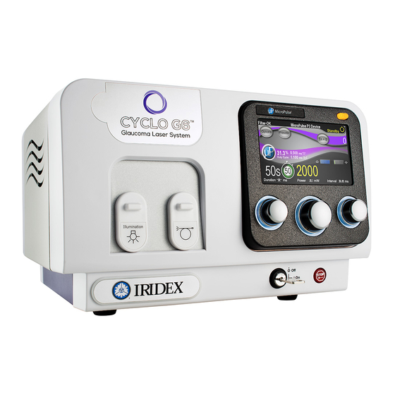
Introduction The IRIDEX Cyclo G6™ Laser System is a semiconductor diode laser that delivers true continuous wave infrared (810 nm) laser light for ophthalmic applications. Improper use of the laser system can result in adverse effects. Follow the instructions for use described in this operator manual. -
Page 6: Pulse Types
MicroPulse (P) is a laser delivery consisting of a group of microsecond bursts. P Duration Duty Cycle%= × P P Interval Duration P MicroPulse Interval Pulse Envelope Duration Time (ms) Pulse Envelope Interval P Duration ™ 2 IRIDEX Cyclo G6 Laser System Operator Manual 66294-EN Rev D... - Page 7 ® MicroPulse is typically used to administer subvisible threshold laser treatments to macular and perimacular targets. When used here, the terms “subvisible”, “subvisible threshold” or “subthreshold” denote that the desired endpoint is one in which treated tissue offers no ophthalmoscopically observable laser effects. Nevertheless, studies using 810 nm lasers have confirmed that subvisible laser treatment strategies can be clinically effective while inducing no changes discernible by slit lamp observation, fluorescein angiography (FA), fundus autofluorescence (FAF), or at any time postoperatively.
-
Page 8: References
22. Parodi MB, Spasse S, Iacono P, Di Stefano G, Canziani T, Ravalico G: Subthreshold Grid Laser Treatment of Macular Edema Secondary to Branch Retinal Vein Occlusion with Micropulse Infrared (810 Nanometer) Diode Laser. Ophthalmology 2006;113(12):2237-42. ™ 4 IRIDEX Cyclo G6 Laser System Operator Manual 66294-EN Rev D... -
Page 9: Indication For Use
The Family of IRIDEX IQ Laser Systems (IQ 532 [532nm], IQ 577 [577nm], IQ 630-670 [630nm-670nm], IQ 810 [810nm] [IRIDEX Cyclo G6 Laser System]) and the hand pieces, delivery devices & accessories that are or LongPulse™ mode. Intended for soft ®... - Page 10 Laser Settings CAUTION: The following treatment parameters are those reported by physicians using IRIDEX products, or like products, either in published literature or reported directly to IRIDEX. These treatment parameters are presented as guidance ultimately it is the physician’s responsibility to determine safe treatment parameters that will be used on patients on a case by case basis.
-
Page 11: References
References ™ *G-P ROBE 1. Gaasterland DE. Diode Laser Cyclophotocoagulation. Glaucoma Today 2009 Mar:35-39. 2. Gaasterland DE, Radcliffe NM, Vold SD, Kammer JA. Reconsidering Transscleral Cyclophotocoagulation. Supplement to Glaucoma Today 2012 Jan-Feb:1-11 3. Kraus CL, Tychsen L, Lueder GT, Culican SM. Comparison of the Effectiveness and Safety of Transscleral Cyclophotocoagulation and Endoscopic Cyclophotocoagulation in Pediatric Glaucoma. -
Page 12: Warnings And Cautions
Laser plume may contain viable tissue particulates. Keep the protective cap over the fiber-optic connector when the delivery device is not in use. ™ 8 IRIDEX Cyclo G6 Laser System Operator Manual 66294-EN Rev D... -
Page 13: Iridex Corporation Contact Information
Use only IRIDEX delivery devices with the IRIDEX laser system. Use of a non-IRIDEX delivery device may result in unreliable operation or inaccurate delivery of laser power. This Warranty and Service agreement does not cover any damage or defect caused by the use of non-IRIDEX devices. -
Page 14: Setup
Setup Unpacking the System Make sure you have all components that were ordered. Check components for damage before use. NOTE: Contact your local IRIDEX Customer Service Representative if there are problems with your order. Laser Wireless Remote Control Footswitch (optional) -
Page 15: Choosing A Location
Choosing a Location Choose a well-ventilated location within the specified operating range of the console. Place the laser system on a table or on existing operating room equipment. Allow at least 5 cm (2 in.) of clearance on each side. In the US, this equipment must be connected to an electrical supply source at 120V or 240V with a center tap. - Page 16 Cyclo G6™ Rear Panel Footswitch Remote and Remote Interlock Auxiliary AC Power Expansion Contact Inlet Port Terminals ™ 12 IRIDEX Cyclo G6 Laser System Operator Manual 66294-EN Rev D...
-
Page 17: Operation
Operation Front Panel Controls Touchscreen Display Treat/Standby Button Illumination & Fiber ports (see caution below) Control Knobs (3) Keyswitch Emergency Stop Button CAUTION: When no delivery device is attached to the system, ensure that the illumination and fiber ports are closed. Powering the Laser On and Off •... -
Page 18: Treating Patients
6. Disconnect the delivery device(s). 7. Dispose of the delivery device, it is single-use. 8. If a contact lens was used, handle the lens according to the manufacturer’s instructions. ™ 14 IRIDEX Cyclo G6 Laser System Operator Manual 66294-EN Rev D... -
Page 19: Using The Laser System
Using the Laser System System Interface Touchscreen Displays current parameter and functions, and acts as the interface to select screens Interface or parameters. Control knobs Used to adjust parameters on the screen. Laser Button Toggles between laser Ready and Standby modes. 66294-EN Rev D Operation... - Page 20 Except during actual treatment, the laser must always be in Standby mode. Maintaining the laser in Standby mode prevents accidental laser exposure if the footswitch is inadvertently pressed. ™ 16 IRIDEX Cyclo G6 Laser System Operator Manual 66294-EN Rev D...
- Page 21 LLUMINATION IMING ETTINGS Illumination and Aiming Beam intensity. Use control knobs to adjust. Save changes and return to previous screen. ULSE ® ICRO ETTINGS Turn MicroPulse ON or OFF. ® Select preset values for Duty Cycle. MicroPulse duration and Interval parameters update automatically.
- Page 22 Selection button to load highlighted preset and go to Standby screen. Cancel loading preset selection and return to Standby screen. Go to Presets Screen to view, update and/or select preset parameters. ™ 18 IRIDEX Cyclo G6 Laser System Operator Manual 66294-EN Rev D...
- Page 23 Presets Screen To access the Presets screen, at the Preset Menu, touch V Go to Previous/Next Preset. ® (Optional) Adjust MicroPulse settings. Use control knobs to select pulse duration, power, and interval. Displays Preset name. Press to enter Keyboard mode. Save changes and go to Treat screen.
- Page 24 Select: letters, numbers, or symbols. Displays Preset name. Deletes characters in Preset Name field. Switch between uppercase and lowercase. Save changes. Cancel changes and return to Presets screen. ™ 20 IRIDEX Cyclo G6 Laser System Operator Manual 66294-EN Rev D...
- Page 25 Options Screen To access the Options screen, Touch O PTIONS Set aiming beam in Standby: ON or OFF. Set aiming beam in Treat: • OFF: Aiming beam OFF while footswitch is depressed. • ON: ON at all times. • Blink: Blink at fixed rate (not synchronized with laser settings). Set voice prompt: Female, Male, OFF.
-
Page 26: Troubleshooting
• If possible, connect another IRIDEX delivery device and place the console in Treat mode. If the aiming beam is still not visible, contact your local IRIDEX Technical Support representative. • Verify that the remote interlock has not been activated. -
Page 27: Error Messages
User Action: Turn the keyswitch Off and then On. The system will attempt to correct itself. If the error persists, write down the error code (example: E05002) and contact IRIDEX Service. Error Code... - Page 28 You can clear the message; however, you cannot fire the laser until a delivery device or SmartKey is connected. Refer to the table below for corrective actions. If a user action does not correct the problem, contact IRIDEX Service. Event / Error Code...
-
Page 29: Maintenance
Verifying the Power Calibration To ensure that calibration meets the requirements of the National Institute of Standards and Technology (NIST), the laser treatment power is calibrated at the IRIDEX factory with a power meter and an IRIDEX delivery device with previously measured transmission. - Page 30 5. Set the laser Power to 200 mW. 6. Place the laser in Treat mode. 7. Direct the aiming beam from the IRIDEX delivery device onto the power sensor, following the power meter instructions for sampling the laser power. 8. Actuate the footswitch to deliver the treatment beam. Power measured by the meter should stabilize before the end of the timed exposure.
- Page 31 ® Power Measurements using a MicroPulse Delivery Device ® ® Exposure MicroPulse MicroPulse Indicated Measured Acceptable Duration (ms) Duration (ms) Interval (ms) Power (mW) Power (mW) Range (mW) 1000–3000 80-120 1000–3000 200-300 1000–3000 1000 400-600 1000–3000 2000 800-1200 Data for power measurement equipment: Calibration Date Meter Model and Serial Number: Calibrated By:...
-
Page 32: Safety And Compliance
Eye safety filters protect the physician from backscattered treatment laser light. Integral eye safety filters are permanently installed in the Slit Lamp Adapter, LIO, EasyFit Adapter, IRIDEX Integrated Slit Lamp Workstation, and SL130 Integrated Slit Lamp Workstation. For endophotocoagulation, a separate discrete eye safety filter assembly must be installed into each viewing path of the operating microscope. - Page 33 Numerical aperture is equal to the sine of the half-angle of the emerging laser beam. Maximum available laser power and associated NA vary with each delivery device, resulting in unique NOHD values for each delivery device. Cyclo G6™ NOHD Values for Delivery Devices Maximum Power...
-
Page 34: Safety Compliance
CE marked devices comply with all requirements of the European Medical Device Directive MDD 93/42/EEC. The IRIDEX Cyclo G6™ uses Medical grade, universal input switching power supply that meets EN 60601-1 performance and safety requirements. A removable power cord provides a means of isolating the equipment from the supply main. -
Page 35: Labels
Labels NOTE: The actual label may vary with laser model. Serial Number (Rear Panel) Ground (bottom of laser) Footswitch Wireless Receiver 66294-EN Rev D Safety and Compliance... - Page 36 Remote Control SERIALIZE #s: RCI0100 to RCI9999 Laser Warning Rear Panel of Console ™ 32 IRIDEX Cyclo G6 Laser System Operator Manual 66294-EN Rev D...
-
Page 37: Symbols (As Applicable)
Symbols (As Applicable) Aiming beam Angle Aspirating probe Caution Audible signal CE marking Do not use if package Duration Connector type is damaged Duration with Emergency stop ETL mark MicroPulse Authorized Sterilized using Expiration date representative in the ethylene oxide European Community Footswitch Footswitch in... - Page 38 66294-EN Rev D Safety and Compliance...
- Page 39 Item or surface can CSA Group Mark Warning, replace with be hot and should not fuses as indicated be touched without Health Canada taking care Warning of Optical Radiation ™ 34 IRIDEX Cyclo G6 Laser System Operator Manual 66294-EN Rev D...
-
Page 40: Specifications
Specifications Specification Description Treatment wavelength 810 nm infrared 50 – 3000 mW, depending on delivery device Treatment power Exposure Duration CW-Pulse™: 10 ms – 9000 ms in 606 increments and continuous pulse up to 60 seconds ® MicroPulse 0.05 – 1.0 ms in 19 increments Exposure interval CW-Pulse™: 10 –... -
Page 41: Wireless Footswitch And Emc
NOTE: The footswitch is designed to operate within 15 feet (5 meters) of the laser. Testing the Batteries NOTE: When batteries need to be replaced, contact your sales representative or IRIDEX Customer Service. The wireless footswitch was designed with a battery life expectancy of 3 – 5 years of normal operation and use. -
Page 42: Emc Safety Information
Connect the laser console into an outlet on a circuit different from that to which the receiver is connected. • Consult IRIDEX Customer Service for help. This Class B digital apparatus meets all requirements of the Canadian Interference-Causing Equipment Regulations. - Page 43 The laser system is suitable for use in all establishments, other than domestic establishments and those directly connected to the public low-voltage power supply network that supplies buildings used for domestic purposes. ™ 38 IRIDEX Cyclo G6 Laser System Operator Manual 66294-EN Rev D...
- Page 44 Guidance and Manufacturer’s Declaration - Immunity This laser system (console and accessories) is intended for use in the electromagnetic environment specified below. The customer or the user of the laser system should assure that it is used in such an environment. Electromagnetic Environment –...
- Page 45 If abnormal performance is observed, additional measures may be necessary, such as reorienting or relocating the laser system. b: Over the frequency range 150 kHz to 80 MHz, field strengths should be less than 3 V/m. ™ 40 IRIDEX Cyclo G6 Laser System Operator Manual 66294-EN Rev D...
- Page 46 Recommended Separation Distances between Portable and Mobile RF Communications Equipment and the Wireless Footswitch The wireless footswitch is intended for use in an electromagnetic environment in which radiated RF disturbances are controlled. The customer or the user of the wireless footswitch can help prevent electromagnetic interference by maintaining a minimum distance between portable and mobile RF communications equipment (transmitters) and the wireless footswitch as recommended below, according to the maximum output power of the communications equipment.
Need help?
Do you have a question about the Cyclo G6 and is the answer not in the manual?
Questions and answers