
Related Manuals for Wavtech LINK4


Summary of Contents for Wavtech LINK4
- Page 1 4-Channel Line Output Converter Summing Ÿ AUX Input Ÿ Multi-Function Remote Owner’s Manual www.wavtech-usa.com...
-
Page 2: Package Contents
This symbol means important instructions. WARNING Failure to heed them can result in serious injury or death. This symbol means important instructions. CAUTION Failure to heed them can result in injury or property damages. WARNING • DO NOT DRIVE WHILE DISTRACTED. Any function that requires your prolonged attention should not be performed while driving. - Page 3 • Œ Power Indicator: This red LED indicates when the link4 is powered on. Once illuminated, there will be a short delay before audio signal output is enabled. During initial power connection, the LED may illuminate for a brief period.
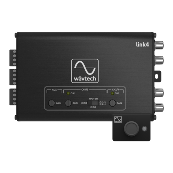
- Page 4 AUX input. Each will be dimly lit just before the onset of clipping, and full bright at clipping. Since the link4 can produce up to 10Vrms output before clipping, it is likely that gain(s) will need to be reduced below the illumination point(s) to match your amplifier(s) maximum input capability or optimize source volume range.
- Page 5 flashing red, solid blue and flashing blue. In the default system Type-1, the only LED indication is solid red when the link4 is powered on. For the other three system types, solid red indicates Main speaker level source is selected and solid blue is for AUX source. Flashing indicates CH3/4 level mode is active for the current source, which will timeout after 5 seconds if no adjustments are made.
-
Page 6: System Examples
Remote Input (REM IN): If the source unit has a remote output wire (provides +12V only when turned on), connect it to the REM IN terminal. If a remote lead is unavailable, the link4 also has an auto turn-on circuit that simultaneously detects audio signal from SPK and AUX inputs as well as DC-offset from SPK inputs. - Page 7 This provides master volume control for AUX input as well as independent CH3/4 level adjustment for both sources. In this 5-channel system example, note that the link4’s CH1/2 output needs to be split with y-adapters for the amplifier’s front/rear channels (unless it has an input select switch) in order to reserve CH3/4 for sub level control.
- Page 8 REM OUT Notes: For factory systems without an available full-range signal, the Link4 can be used to sum 2-way signals together. When Ÿ CH1+3/2+4 is selected for CH1/2’s input, the summed left channel (CH1+3) and right channel (CH2+4) signals are routed to the CH1/2 outputs.
-
Page 9: Installation Notes
Ÿ (size/location, etc.) Subwoofer(s) Ÿ (size/location, etc.) Amplifier(s) Ÿ (location, output voltage, etc.) Other: Ÿ link4 Connections & Settings Installed Location: Ÿ Wiring Ÿ (connection locations, signal type, turn-on mode, etc) Settings Ÿ (gain, max master vol, crossover, etc.) Other: Ÿ... -
Page 10: Specifications
Specifications Max Flat (+0/-1dB) <10Hz to >80kHz Frequency response Extended (+0/-3dB) <5Hz to >100kHz Spk Input 180Ω / 20kΩ Input Impedance AUX Input >50kΩ Spk Input (max-min gain) 2-20Vrms / 4-40Vrms Input Sensitivity AUX Input (max-min gain) 0.5 - 5Vrms Max Input Voltage 40Vrms Spk Input... - Page 11 Warranty & Service Care Wāvtech warrants this product to be free from defects in material and workmanship for a period of one (1) year when purchased from an authorized Wāvtech retailer within the United States. This warranty will be extended to a period of two (2) years when the installation is performed by an authorized Wāvtech retailer.
- Page 12 v0818 ® Wāvtech 7931 E. Pecos Rd Suite 113 Mesa, AZ 85212 (480) 454-7017 ©Copyright 2018 Wāvtech, LLC. All Rights Reserved.
Need help?
Do you have a question about the LINK4 and is the answer not in the manual?
Questions and answers