Advertisement
Quick Links
Specifications Information and Repair Parts Manual
Please read and save this Repair Parts Manual. Read this manual and the General Operating Instructions carefully before attempting to assemble, install, operate
or maintain the product described. Protect yourself and others by observing all safety information. The Safety Instructions are contained in the General Operating
Instructions. Failure to comply with the safety instructions accompanying this product could result in personal injury and/or property damage! Retain instructions
for future reference. AMT reserves the right to discontinue any model or change specifications at any time without incurring any obligation.
©2018 AMT Pump Company, A Subsidiary of The Gorman-Rupp Company, All Rights Reserved.
Periodic maintenance and inspection is required on all pumps to ensure proper operation. Unit must be clear of debris and sediment. Inspect for leaks and loose bolts. Failure to do so
voids warranty.
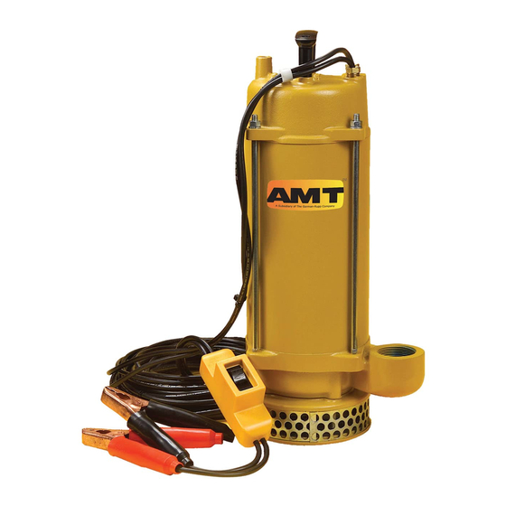
Submersible Pump 12VDC Series
Refer to pump manual 1808-634-00 for General Operating and Safety Instructions.
DESCRIPTION
The AMT Submersible 12VDC pump is designed for use in remote locations without electricity and for emergency back-up during power failure. Unit comes
assembled and requires minimum 55 amp-hour battery for proper operation. For use with non-flammable liquids compatible with pump components.
Read all safety warnings and instructions in this manual completely before installation and start-up of the pump. It is the responsibility of the
purchaser to retain this manual for reference. Failure to comply with the recommendations stated in this manual will damage the pump and void
factory warranty.
1.
Make sure the vehicle and the pump are not in contact during connection.
2.
Do not use power cable for handling unit.
3.
Do not run pump completely dry for extended periods. Damage to shaft seal may result
DANGER:
Not for use with fluids that have a flash point below 100º F
(38º C) (Example: gasoline, alcohol). Sparking could result in death.
OPERATING AND INSTALLATION INSTRUCTIONS
Hose: Since the pump develops relatively low pressure, it is recommended
that non-collapsible hose be used for maximum pumping rates.
Hoisting and Lowering: Attach a line to the metal handle on the top of the
pump for hoisting or lowering the unit. Do not use power cable for handling
unit.
To Operate: Lower unit into liquid to be pumped and activate switch. Do not
run dry; damage to shaft seal will result.
RUNNING TIME: This unit draws about 30 amperes and can be operated about
1 hour on a fully charged 55 amp-hour battery and still permit starting of vehicle
under normal conditions. Caution should be used when running time exceeds
30 or 40 minutes without engine running to recharge battery, particularly in cold
weather when battery efficiency is lowered. Battery size (amt-hour rating) and
the use of other accessories such as lights and radios, etc. must be taken into
consideration for practical running periods without engine running.
OVERLOAD PROTECTION is provided by means of a 40 amp automatic reset
circuit breaker located under top cover.
TROUBLE SHOOTING
NOTE: (Most common cause of failure to run, is due to hardened mud and
sand at impeller.) Remove strainer to check.
Should unit not operate, always check freeness of rotation of impeller by
inserting screwdriver through hole in base plate into slot in end of shaft.
MOTOR WILL NOT RUN:
1.
Poor connection at battery.
2.
Impeller locked with foreign material.
3.
Insufficient impeller clearance.
4.
Damaged power cable or loose connection internally in motor assembly.
5.
Bad switch or circuit breaker. Connect power leads directly to motor leads
to check.
6.
Worn motor brushes or out of position to make contact with armature.
5890-250-00
PERFORMANCE LOW:
1.
Strainer screen partially plugged.
2.
Impeller rubbing. Check freeness of rotation with screwdriver inserted
through hole in base plate into slotted end of shaft.
3.
Battery not fully charged.
4.
Discharge restriction such as kinked hose or excessive discharge head.
MOTOR RUNS BACKWARDS:
1.
Check wiring for correct polarity.
SERVICE & REPAIR INSTRUCTIONS DISASSEMBLY:
Impeller and shaft seal can be inspected and serviced from lower end of
pump by removal of 4 cap screws securing base plate, strainer screen and
suction cover. Screwdriver slot is provided in end of motor shaft to turn shaft
while holding impeller for removal. This permits removal of impeller without
disassembly of upper motor housing to hold motor shaft.
Alternately, there is a shaft extension with two flats on the rear of the motor for
use when the impeller is difficult to remove. The upper motor cover must be
removed to expose this shaft extension.
To service motor, remove 4 hex nuts and bump top cover free from housing
tube. Raise sufficiently to disconnect power cable connections. Slide housing
tube up from pump casing and motor will be exposed for service or removal.
Make certain that wire leads are installed per Figure 1. Install top cover as
indicated by arrow and instruction on top of cover. Make sure wires do not
contact motor shaft when installing motor cover.
Figure 1 - Wiring Diagram
1
5890-DC
2/2019
Advertisement

Related Manuals for AMT Submersible Pump 12VDC Series


Summary of Contents for AMT Submersible Pump 12VDC Series
-
Page 1: Trouble Shooting
DESCRIPTION The AMT Submersible 12VDC pump is designed for use in remote locations without electricity and for emergency back-up during power failure. Unit comes assembled and requires minimum 55 amp-hour battery for proper operation. For use with non-flammable liquids compatible with pump components. - Page 2 5890-DC Specifications Information and Repair Parts Manual Submersible Pump 12VDC Series For Repair Parts contact dealer where pump was purchased. Please provide following information: -Model Number -Serial Number (if any) Part description and number as shown in parts list Figure 2 - Repair Parts Illustrations...
-
Page 3: Repair Parts List
5890-DC Specifications Information and Repair Parts Manual Repair Parts List Description Part Number Self Tapping Screw included with Ref 11 Motor Cover Kit 5890-040-90 Hex Nut included with Ref 4 Handle Kit 5890-100-90 Gland Nut Kit 5890-420-90 (includes Ref. Nos. 5,6 & 7) Gland spacer included with Ref 5 Sealing Ring... - Page 4 5890-DC Specifications Information and Repair Parts Manual 5890-250-00 2/2019...
Need help?
Do you have a question about the Submersible Pump 12VDC Series and is the answer not in the manual?
Questions and answers