Advertisement
Quick Links
Specifications Information and Repair Parts Manual
Please read and save this Repair Parts Manual. Read this manual and the General Operating Instructions carefully before attempting to assemble, install, operate
or maintain the product described. Protect yourself and others by observing all safety information. The Safety Instructions are contained in the General Operating
Instructions. Failure to comply with the safety instructions accompanying this product could result in personal injury and/or property damage! Retain instructions
for future reference. AMT reserves the right to discontinue any model or change specifications at any time without incurring any obligation.
©2017 AMT Pump Company, A Subsidiary of The Gorman-Rupp Company, All Rights Reserved.
Periodic maintenance and inspection is required on all pumps to ensure proper operation. Unit must be clear of debris and sediment. Inspect for leaks and loose bolts. Failure to do so
voids warranty.
Sewage/Trash Pumps
Refer to pump manual 1808-634-00 for General Operating and Safety Instructions.
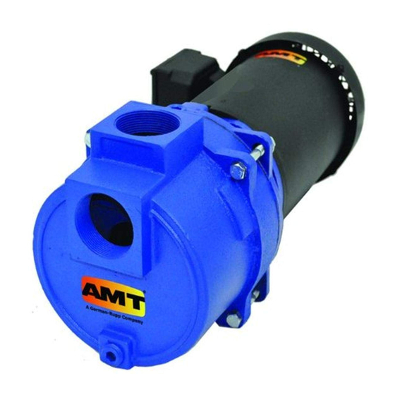
DESCRIPTION
This sewage/trash pump is a heavy duty, centrifugal, motor driven, self-priming (to 20 ft. lift) unit, after initially filling casing with liquid. Pump is equipped with a
silicon carbide mechanical seal, cast iron wear surfaces and a stainless steel clog-resistant impeller. Units are used to handle water containing sewage, stones,
sticks, mud and other solids: maximum diameter ½ the discharge NPT size. Handle liquids from 40º to 180º F (4º to 82º C) for use with nonflammable fluids com-
patible with pump component materials. All units come with built-in suction check valve to aid priming efficiency and easily removable casing/clean out cover and
volute for quick debris clean out. An NPT threaded seal wash port is provided on Models 393A-95, 393B-95, 394G-95, 394H-95, 394J-95, 394K-95 and 399D-95.
Units are powered by totally enclosed fan cooled (TEFC) motors, single or three phase power. Motor includes stainless steel shaft or stainless steel shaft sleeve.
Pumps must be operated in specific ranges as noted on respective curves
on page 3 (Figure 3). Failure to adhere to curve will result in damage and
cavitation to pump thus voiding warranty.
UNPACKING
Refer to Repair Parts Illustration and Repair Parts List to aid in identifying
parts. Unpack and separate all pump components from container making sure
all parts are accounted for.
Package should contain:
1.
Pump and motor completely assembled.
2.
Suction strainer.
3.
Specifications Information & Repair Parts Manual.
4.
General Operating Instructions & Maintenance Manual.
MAINTENANCE
Note: For information pertaining to the motor and motor parts, consult the
motor manual or contact the nearest authorized service representative or the
manufacturer.
Make certain that the unit is disconnected from the power source before
attempting to service or remove any component.
Figure 1 & 2 - Mechanical Seal Replacement
394K-250-00
MECHANICAL SEAL REPLACEMENT
Should the mechanical seal, which consists of a seal seat (stationary) and seal
head (rotating), require replacement, proceed as follows and refer to Repair
Parts illustration that corresponds to your pump model (316A/B = Figure 4,
393A/B = Figure 5, 394G/H/J/K = Figure 6, 399D = Figure 7). The seal should
be replaced if the adapter or impeller is replaced. If the pump is equipped with a
shaft sleeve (JM motor) it may be easier to replace the sleeve with the rotating
seal head.
NOTE: Always replace the seal seat and head as a unit, never replace the seal
seat or seal head individually.
316A & 316B:
1.
Remove four bolts (Ref. No. 9). Pull casing (Ref. No. 1) from adapter.
2.
Remove casing O-ring (Ref. No. 7). Remove screw (Ref. No. 11). Pull
volute (Ref. No. 2) from adapter.
3.
Remove impeller lock nut (Ref. No. 18). Unscrew impeller (Ref. No. 3)
from motor shaft (Ref. No. 17). Use a rubber mallet or soft block of wood
to loosen impeller. Turn it counterclockwise.
4.
Remove the impeller shim(s) (Ref. No. 4).
5.
Remove the seal head (Ref. No. 5) from motor shaft.
6.
Remove four screws (Ref. No. 13). Pull adapter (Ref. No. 8) from motor.
7.
Push seal seat (Ref. No. 6) from adapter. Clean seal seat bore in adapter.
8.
Check motor shaft for damage. Motor shaft must be smooth and free from
scratches or score marks. Clean shaft of any debris or remnants of old
seal head.
393:
1.
Remove four bolts (Ref. No. 9). Pull casing (Ref. No. 1) from adapter.
2.
Remove casing O-ring (Ref. No. 7). Remove two screws (Ref. No. 11).
Pull volute (Ref. No. 2) from adapter.
3.
Using a hex key remove impeller screw (Ref. No. 18) and O-ring (Ref. No.
25). Slide impeller (Ref. No. 3) from motor shaft (Ref. No. 17).
4.
Remove the impeller shim(s) (Ref. No. 4) and impeller drive key (Ref. No.
21)
5.
Slide the seal head (Ref. No. 5) off the shaft sleeve (Ref. No. 19).
6.
Remove four screws (Ref. No. 13). Pull adapter (Ref. No. 8) from motor.
7.
Push seal seat (Ref. No. 6) from adapter. Clean seal seat bore in adapter.
1
316A-95, 316B-95, 393A-95, 393B-95,
394G-95, 394H-5, 394J-95, 394K-95, 399D-95
1/2017
Advertisement

Related Manuals for AMT 316A-95


Summary of Contents for AMT 316A-95
-
Page 1: Mechanical Seal Replacement
Instructions. Failure to comply with the safety instructions accompanying this product could result in personal injury and/or property damage! Retain instructions for future reference. AMT reserves the right to discontinue any model or change specifications at any time without incurring any obligation. -
Page 2: Shim Adjustment
316A-95, 316B-95, 393A-95, 393B-95, Specifications Information and Repair Parts Manual 394G-95, 394H-5, 394J-95, 394K-95, 399D-95 Sewage/Trash Pumps Remove the shaft sleeve from the motor shaft if the sleeve is damaged or 17. 316; screw impeller back in place. Tighten until it is seated against shims scored. - Page 3 316A-95, 316B-95, 393A-95, 393B-95, Specifications Information and Repair Parts Manual 394G-95, 394H-5, 394J-95, 394K-95, 399D-95 Sewage/Trash Pumps NOTE: When the clearance between the impeller and the volute exceeds 1/16” at the face of the impeller or 1/8” on the outside diameter of the impeller, it may be necessary to take corrective action.
- Page 4 316A-95, 316B-95, 393A-95, 393B-95, Specifications Information and Repair Parts Manual 394G-95, 394H-5, 394J-95, 394K-95, 399D-95 Sewage/Trash Pumps Figure 3 - Performance Curve 394K-250-00 1/2017...
- Page 5 316A-95, 316B-95, 393A-95, 393B-95, Specifications Information and Repair Parts Manual 394G-95, 394H-5, 394J-95, 394K-95, 399D-95 Sewage/Trash Pumps For Repair Parts contact dealer where pump was purchased. Please provide following information: -Model Number -Serial Number (if any) Part description and number as shown in parts list...
-
Page 6: Repair Parts List
316A-95, 316B-95, 393A-95, 393B-95, Specifications Information and Repair Parts Manual 394G-95, 394H-5, 394J-95, 394K-95, 399D-95 Repair Parts List Part Number for Models Description 316A-95 316B-95 Casing 2111-001-02 2111-001-02 Volute 3163-150-09 3163-150-09 Impeller 3163-011-01 3163-011-01 Impeller Shim Set 1806-044-90 1806-044-90 5 & 6 Seal Assembly –... - Page 7 316A-95, 316B-95, 393A-95, 393B-95, Specifications Information and Repair Parts Manual 394G-95, 394H-5, 394J-95, 394K-95, 399D-95 Sewage/Trash Pumps For Repair Parts contact dealer where pump was purchased. Please provide following information: -Model Number -Serial Number (if any) Part description and number as shown in parts list...
- Page 8 316A-95, 316B-95, 393A-95, 393B-95, Specifications Information and Repair Parts Manual 394G-95, 394H-5, 394J-95, 394K-95, 399D-95 Repair Parts List Part Number for Models Description 393A-95 393B-95 Casing 2112-001-02 2112-001-02 Volute 2182-002-00 2182-002-00 Impeller Kit 3935-011-98 3935-011-98 (Includes Ref. Nos. 3, 4, 18, & 21)
- Page 9 316A-95, 316B-95, 393A-95, 393B-95, Specifications Information and Repair Parts Manual 394G-95, 394H-5, 394J-95, 394K-95, 399D-95 Sewage/Trash Pumps For Repair Parts contact dealer where pump was purchased. Please provide following information: -Model Number -Serial Number (if any) Part description and number as shown in parts list...
- Page 10 316A-95, 316B-95, 393A-95, 393B-95, Specifications Information and Repair Parts Manual 394G-95, 394H-5, 394J-95, 394K-95, 399D-95 Repair Parts List Part Number for Models Description 394G-95 394H-95 Motor 1627-353-00 1626-079-00 Adapter Kit 394G-030-95 394G-030-95 (Includes Ref. Nos. 2, 3, 4, & 5) 3/8-16 Hex Head Flange Screw Incl.
- Page 11 316A-95, 316B-95, 393A-95, 393B-95, Specifications Information and Repair Parts Manual 394G-95, 394H-5, 394J-95, 394K-95, 399D-95 Sewage/Trash Pumps For Repair Parts contact dealer where pump was purchased. Please provide following information: -Model Number -Serial Number (if any) Part description and number as shown in parts list...
- Page 12 316A-95, 316B-95, 393A-95, 393B-95, Specifications Information and Repair Parts Manual 394G-95, 394H-5, 394J-95, 394K-95, 399D-95 Repair Parts List Part Number for Models 394K-95 Description 394J-95 399D-95 Motor - 1-Phase 1626-080-00 Motor - 3-Phase 1627-354-00 1627-355-00 Adapter Kit 394H-030-95 394H-030-95 (Includes Ref. Nos. 2, 3, 4, & 5) 1/2-13 Hex Head Flange Screw Incl.
- Page 13 316A-95, 316B-95, 393A-95, 393B-95, Specifications Information and Repair Parts Manual 394G-95, 394H-5, 394J-95, 394K-95, 399D-95 NOTES: 394K-250-00 1/2017...
- Page 14 316A-95, 316B-95, 393A-95, 393B-95, Specifications Information and Repair Parts Manual 394G-95, 394H-5, 394J-95, 394K-95, 399D-95 NOTES: 394K-250-00 1/2017...
- Page 16 www.amtpump.com...
Need help?
Do you have a question about the 316A-95 and is the answer not in the manual?
Questions and answers
How often should they be lubed? And what type of Lubricant should be used.