Table of Contents
Advertisement
Advertisement
Table of Contents

Related Manuals for Megger IDAX Series


Summary of Contents for Megger IDAX Series
- Page 1 IDAX User's Manual © 2009 Megger AB...
-
Page 2: Table Of Contents
........................... 70 4 (365) Specimen capacitance below limit ........................... 70 5 (366) Specimen capacitance above limit ........................... 71 6 (367) Measured DC current > MaxDCCurrent ........................... 71 7 (368) Measured hum current > MaxHumCurrent ........................... 71 Index © 2009 Megger AB... -
Page 3: Part I Idax
The IDAX-300 system applies sinusoidal shaped voltages at different frequencies across the test object and simultaneously measures the current through it. The output voltage is either taken from a 10 V arbitrary waveform generator or from a 200 V arbitrary waveform peak peak generator. © 2009 Megger AB... - Page 4 -40°C to 70°C / -40°F to +158°F Storage Ambient Temp: 20% - 95% RH, non-condensing Humidity: CE Standards: IEC61010 (LVD) EN61326 (EMC) PC Requirements Operating System: Windows 2000/ XP / Vista Pentium 500 MHz/512 Mb or better CPU/RAM: Interface: USB 2.0 © 2009 Megger AB...
- Page 5 IDAX 1.1.2 System and Accessories 1.1.2.1 IDAX-300 System and Accessories IDAX-300 Transport case Cables © 2009 Megger AB...
- Page 6 Make sure that the mains voltage selected on the selector switch located on the back panel corresponds to the voltage level before connecting the mains. Refer all servicing to qualified service personnel. If you need to return your IDAX, please use either the original crate or one of equivalent strength. © 2009 Megger AB...
-
Page 7: Instrument Panels
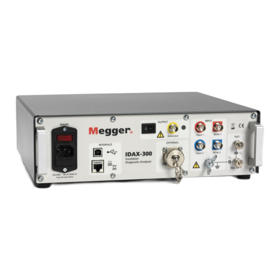
For connecting to mains outlet. c) Fuse Use small screwdriver to gently pry out to change the fuse, F1, 2A slow blow. Interface d) USB Port for connecting computer e) ETHERNET RJ45 connector for Ethernet connection via twisted pair cable. © 2009 Megger AB... - Page 8 Connector for external amplifier Input j) Input 1 and Sense 1 First input channels. k) Input 2 and Sense 2 Second input channels. l) Protective ground Connector for connection to station ground. m) Test Test inputs. © 2009 Megger AB...
-
Page 9: Software Installation
The voltage (and the current) is generated by a voltage source. There are currently two internal voltage sources available in the IDAX system, which can deliver a maximum peak output of 10 Vpeak and 200 Vpeak, respectively. The voltage is measured by means of a voltmeter and © 2009 Megger AB... - Page 10 Another model, more often used in insulation diagnostics, is the complex capacitance model describing the insulation impedance as a complex capacitance, where the imaginary part of the capacitance represents the losses. The complex capacitance model is defined as follows: where © 2009 Megger AB...
- Page 11 "material capacitance", the permittivity, is a complex function describing both the capacitance and the loss. Whereas in the conductive model the capacitance is described by a permittivity and the loss by a conductivity (or resistivity). The dielectric and resistive models are derived as follows: © 2009 Megger AB...
-
Page 12: Getting Started With Idax
This procedure is also a good test to perform whenever a confirmation of the proper functioning of the instrument is required. This test is executed using the standard equipment delivered with IDAX. Before starting to use IDAX certain preparatory procedures must be followed. © 2009 Megger AB... - Page 13 7. Create new measurement sequence selecting Measurement Sequence from menu File / New. Arbitrary name can be entered as Measurement Sequence, for example "Getting Started" and press OK. New measurement sequence with corresponding Measurement Plan files will appear in Test Browser. © 2009 Megger AB...
- Page 14 The specimen to be measured using the built-in capacitance box built into the system that terminates at the front panel. The respective capacitances are: = ~2.5 nF = ~4.7 nF Warning! The measurement system can generate hazardous and even lethal voltages. Carefully read "Safety precautions". Ungrounded Specimen Test (UST) Measurement © 2009 Megger AB...
- Page 15 4. Remove possible ground connections from somewhere. 5. Turn on the output switch activate the output and then start the measurement. 6. Wait until measurement is finished or abort earlier by stopping the measurement. Grounded Specimen Test (GST) Measurement © 2009 Megger AB...
- Page 16 (Red) (blue) Yellow) GST-Guard-1+2 UST-1 GST-Guard-1+2 IDAX-206 (two winding transformer) Test no. Measure Configuration Energize Channel 1 (Hi, Red) (Lo, Blue) GST-Guard GST-Guard IDAX-300 (three winding transformer) Test no. Measure Configuration Energize Channel 1 Channel 2 © 2009 Megger AB...
- Page 17 1. By pressing <F4> on the keyboard, Results window can be activated if not already active and the measurement progress can be viewed when selecting Graph tab. The graph shows the dissipation factor for the Test Capacitor in the frequency range 0.1 - 1000 Hz . © 2009 Megger AB...
- Page 18 You can press stop button or, on the IDAX-206, the OUTPUT OFF button. On the IDAX-206 a lit green READY LED on the front panel indicates that the measurement is stopped or finished. © 2009 Megger AB...
- Page 19 See also how to select models in sections "Configuration / Models" "Sample Modelling". The results can be viewed using three additional tabs: Graph, Table and 50/60 Hz data as shown in pictures below. Graph tab is active © 2009 Megger AB...
- Page 20 1. Select Configuration / Models in Results window and all available models will be presented as shown below. In this picture, both the "Dielectric" and "C, PF, Tan-delta" models are ticked. Select the desired models and click OK. © 2009 Megger AB...
-
Page 21: Idax System Control
The IDAX System Control performs a measurement according to commands pre-arranged in a Measurement plan or command file (C-file), using programming syntax described in IDAX Command and Variable References. The Measurement plan used is available in Results tab Measurement plan. © 2009 Megger AB... - Page 22 IDAX unit. If you are not connected and the software needs to connect to the IDAX unit it will be done automatically. 1.6.3 Oscilloscope The Oscilloscope displays the signals present on channel 0 (white, Ch0) and channel 1 (red, Ch1) inputs of the analogue IO unit. © 2009 Megger AB...
- Page 23 Control, which opens a file opening dialog. The selected language file, *.lng, is loaded and it will be used after restarting the IDAX program. Each language has its own language file, *.lng, and all language files are located in the directory D:\IDA\Language files\. © 2009 Megger AB...
- Page 24 Capacitance between ----- ----- ----- middle shield and outer (Farad) shield 1.6.6 About In "About" window the software versions of installed IDAX system, its program components and information about the operating system are displayed. © 2009 Megger AB...
-
Page 25: Part Ii Results User Interface
Interaction with the program is done via windows and toolbar menu, the functions are described in "Results Menus and Commands" Results window is divided into two sections: § Test Browser (left-side) § Measurement Plan and presentation of the measurement results in graphical and table format (right-side) © 2009 Megger AB... -
Page 26: Results Menus And Commands
View Menu Selection of presentation form Configuration Menu Configuration of Results window settings Help Menu On-line Help Icon menu Icon menu is designed for easier navigation and operations with Test Browser. Open measurement Close measurement Save © 2009 Megger AB... - Page 27 2.1.1.1.1 File / New / Object New object is created if the object to be measured is not among those in Test Browser. 1. Select New / Object from File menu which opens New Object dialog © 2009 Megger AB...
- Page 28 IDAX User's Manual 2. Select appropriate object template by using Browse button and press Open 3. Enter name for the new object, for example, "Test capacitor.obj" and press OK. © 2009 Megger AB...
- Page 29 See also section "IDAX 206 Commands and Variables". 2.1.1.1.3 File / New / Object Template 1. From View menu select View / Browse Object Templates 2. From File menu select File / New / Object Template, enter a name for new template and © 2009 Megger AB...
- Page 30 2. New Measurement Sequence will be automatically assigned a name in form of date as shown below (date has the format according to International Standard ISO 8601). The name for Measurement Sequence (i.e. "First Test" as in picture below) is optional. © 2009 Megger AB...
- Page 31 It invokes a dialog window where user can manipulate with available Measurement Templates (see picture below). This dialog window can be also invoked by right mouse click on selected object and choosing Add/Remove Templates from the menu which appears as shown below. © 2009 Megger AB...
- Page 32 Save any changes made to the current template or Measurement Plan. 2.1.1.7 File / Save As Select template which is to be saved under new name. Invoke Save As dialog from menu File / Save As... © 2009 Megger AB...
- Page 33 Structure. If Results program is opened as an independent program and the data files are temporary opened, then closing Results program, user is asked if the opened files should be imported into the existing data structure. © 2009 Megger AB...
- Page 34 1. From menu File / Import / File to Structure invoke import dialog. 2. Select the directory where measurement(s) to be imported are located. 3. Select Object under which the measurement must be imported. © 2009 Megger AB...
- Page 35 Results User Interface 4. Select the Measurement Sequence. 5. Select measurement(s) to be imported. By default all measurements located in given directory are imported. Deselect those which not to import by unchecking appropriate check boxes. © 2009 Megger AB...
- Page 36 / Measurement Templates: 1. Choose directory where template(s) to be imported are located by typing in the path manually or using Browse button. 2. Select template(s) to be imported from available templates in the left hand side. © 2009 Megger AB...
- Page 37 1. Choose directory where the template(s) to be imported are located by typing in the path manually or using Browse button. 2. Select the template(s) to be imported from available templates in the left hand side. 3. Press Add button or double click by left mouse button on chosen template. © 2009 Megger AB...
- Page 38 Decimal separator. The Format option allows user to remove the header of the file, which makes it easier to import the data into another program. Decimal numbers are written in the file using chosen Decimal separator option - point or comma. © 2009 Megger AB...
- Page 39 Results User Interface Moreover, it is possible to export also the measurement file itself by checking checkbox "Include D-File", which may be favourable when exporting to floppy disk. 2.1.1.10.3 Header Export with header © 2009 Megger AB...
- Page 40 IDAX User's Manual Export without header 2.1.1.10.4 Point/Comma Point as a decimal separator Comma as a decimal separator © 2009 Megger AB...
- Page 41 3. Choose destination directory typing in the path or using Browse button. 4. Press OK button. To remove a template: 1. Select it from the right hand side from selected templates. 2. Press Remove button or double click by left mouse button. © 2009 Megger AB...
- Page 42 · calculated values such as equivalent current, dissipated power, power factor and capacitance at 10 kV and at 50/60 Hz, · table containing the data, which are selected in the Results window, · graphical presentation of the measurement. © 2009 Megger AB...
- Page 43 When invoking List&Label report generator, a dialog window allows for choosing between various options as shown in the picture below. If there are already prepared report file(s) they will be listed in the left side of the dialog window and can be selected to work with. © 2009 Megger AB...
- Page 44 Modify in selected report file can be done. It means that the layout, appearance, etc. can be changed. Compile Preview selected report file with the users data. Printing is done using MS Word print options. Close Close Report dialog © 2009 Megger AB...
- Page 45 When a executable application is selected, the name of the executable is added to the Send to... menu as shown below, where MODS has been chosen as application where data are to be sent. © 2009 Megger AB...
- Page 46 3. Type new file or folder name and press Enter 2.1.1.15 File / Delete File/Folder 1. Select the file or folder to be deleted 2. Choose Delete File/Folder from menu or right-click on the file or folder. A pop-up window will appear: © 2009 Megger AB...
- Page 47 Reverse the effect of the last action performed, such as typing, deleting or formatting text, etc. 2.1.2.2 Edit / Copy Shortcut keys: Ctrl+C Place a duplicate of the selected text or object(s) onto the Clipboard where it can be pasted elsewhere. © 2009 Megger AB...
- Page 48 · the sweeps to be displayed also depends on selected position in Test Browser. Position in Test Browser Displayed sweeps Object All opened measurements under this object are displayed Measurement sequence All opened measurements in this sequence are displayed All sweeps in this file are displayed Measurement file © 2009 Megger AB...
- Page 49 Zooming in into a selected area Zoom out Returning to full graph 2.1.3.1 Diagram / Zoom In Shortcut keys: Ctrl+I 1. The Zoom In command allows user to select a rectangular area of the by dragging a rectangle with the mouse. © 2009 Megger AB...
- Page 50 IDAX User's Manual 2. The marked area will the be magnified to cover the entire graph area as shown below. © 2009 Megger AB...
- Page 51 C-file (*.icf). This text file contains all information specific for the measurement in question, and is in its entirety saved in the data file (*.idf) before the measurement data. Displayed content of Information tab depends on selected place in Test Browser. There are several possibilities: · Object selected · Measurement Sequence selected © 2009 Megger AB...
- Page 52 Measurement Templates) and given object. Measurement Template(s) can be edited using also Text view mode. The changes made here will, however, be unique for the given object only. Permanent changes must be made in Measurement Template(s). © 2009 Megger AB...
- Page 53 Text view mode. In the Text view mode appearance of the Measurement Plan view can be specified, thus hiding irrelevant information from the user. The changes made here will, however, be unique for the given measurement. Permanent changes must be made in Measurement Template(s). Information - Measurement Data © 2009 Megger AB...
- Page 54 PF, capacitance, C and others (see also Configuration / Models). By clicking right mouse button on a measurement point the properties of this point are shown in Properties box in left lower corner of Results window. © 2009 Megger AB...
- Page 55 2.1.4.8 View / 50/60 Hz Data Measured values When a frequency sweep is performed, the measurements are done at certain pre-defined frequencies. Due to possible interferences at power frequency (50 or 60 Hz) it is generally © 2009 Megger AB...
- Page 56 Select an external program for data analysis Models Display available models for presentation of results 2.1.5.1 Configuration / Information Editing of Measurement and Object Templates and Measurement Plans in Text View mode can be facilitated by means of this dialog window. © 2009 Megger AB...
- Page 57 4. Font... allows user to select the fonts to be used in Text view of Measurement or Object Templates and Measurement Plan. 2.1.5.2 Configuration / Graph Allows user to configure appearance of graphical output Menu commands Description © 2009 Megger AB...
- Page 58 For grid settings, three options are available: § None, no grid is shown. § Small, also called tics. Only an indication at the axis, no lines in the graph. § Full, all lines are displayed in the graph. © 2009 Megger AB...
- Page 59 Changes between Prefix or Scientific notation in the Graph/Table. 2.1.5.2.2.7 Title Here the title for the graph in Results can be written. If Auto is checked, the title of the measurement will be displayed for the measurement. If more than one measurements are © 2009 Megger AB...
- Page 60 § 50 Hz, e.g. Europe, Australia, most part of Africa and Asia § 60 Hz, e.g. USA, Canada, Mexico, certain countries in South America 3) showing interpolated 10 kV equivalents for current, dissipated power, Power Factor and capacitance © 2009 Megger AB...
- Page 61 Ctrl+M Command Configuration / Models... invokes a window where available models for presentation of measurement results are shown. Different models can be selected and the corresponding results in graphical or text format will be simultaneously displayed. © 2009 Megger AB...
- Page 62 Below the Dielectric and C, PF, Tan-Delta models are chosen to be used in Results and e¢ as a parameter is displayed in the graph. 2.1.6 Impedance models The following impedance models and their parameters are available: © 2009 Megger AB...
-
Page 63: Test Browser
Microsoft Windows Explorer. The main purpose of the Test Browser is to facilitate: § navigation between already performed measurements, Object and Measurement Templates § organisation of new measurements on the existing or new objects § creation and editing Measurement and Object Templates © 2009 Megger AB... - Page 64 IDAX is started by pressing ON. · When measurement is started, the command file is replaced by a data file containing both information from the command file and measurement data. Finished measurement can be © 2009 Megger AB...
- Page 65 § C2, H1 - measurement of bushing H1 insulation between test tap and ground sleeve, C2 § C2, H2 - measurement of bushing H2 insulation between test tap and ground sleeve, C2 § C2, H3 - measurement of bushing H3 insulation between test tap and ground sleeve, C2 © 2009 Megger AB...
-
Page 66: Part Iii Idax Error Messages
File name not specified file dialog. Specify a file name. Not string A string variable is expected. Could not open file: Wrong file name, file is missing or path is incorrect. Could not open or create Problem accessing Windows Registry. © 2009 Megger AB... - Page 67 "VoltageSource" not "VoltageSource" must be assigned. See User's assigned Manual for options. "FileType" not assigned "FileType" must be assigned. See User's Manual for options. "SpecVersion" not assigned "SpecVersion" must be assigned. See User's Manual for options © 2009 Megger AB...
- Page 68 Measured data was not properly added to the D-file. Invalid voltage The desired voltage is out of the specified limits. Possible typing error in the C-file. Invalid current The applied settings results in a current that is too © 2009 Megger AB...
-
Page 69: 364) Measured Capacitances Don't Match
No information to show The information dialog could not display the information. Cannot read from A:\ Results cannot read from floppy disk. Possibly (floppy) damaged floppy. Cannot read from drive Results cannot read from specified drive. © 2009 Megger AB... - Page 70 Ground electrode is connected to ground (365) Specimen capacitance below limit Measured capacitance below limit specified in C-file by MinSpecimenC. Possible reasons and countermeasures 1) Measured capacitance higher than 10 pF. © 2009 Megger AB...
- Page 71 1) Level of interferences is very high: § try to reduce the influence of interferences by placing measuring cables close to each other and avoiding cable loops § increase the limit for hum current set by MaxHumCurrent © 2009 Megger AB...
-
Page 72: Index
- F - Information Models 56, 61 File Power Data Add Templates Power Frequency Data Add/Remove Templates Send to... Close Measurement 27, 32 Table 56, 60 Delete File/Folder 27, 46 Current Exit 27, 47 Range Export Import © 2009 Megger AB... - Page 73 - I - - O - IDAX-206 System and Accessories IDAX-206 System Control Object Templates Comments Oscilloscope Message Window Chanell checkboxes Oscilloscope Grid Selftest Horizontal control Impedance Roll Measurement Vertical control Models Output voltage Impedance Models © 2009 Megger AB...
- Page 74 Test Browser User Interface View Menu - S - Safety Scale Scientific Settings for Graph Specifications - T - Table Tab Temperature Operating Storage Test Browser Data Structure Measurement Templates Object Templates - U - Unit © 2009 Megger AB...
Need help?
Do you have a question about the IDAX Series and is the answer not in the manual?
Questions and answers