Table of Contents
Advertisement
Available languages
Available languages
Advertisement
Table of Contents

Subscribe to Our Youtube Channel
Related Manuals for Ksenia lares 4.0 40


Summary of Contents for Ksenia lares 4.0 40
- Page 1 INSTALLAZIONE E USO INSTALLATION AND USE MANUAL Ksenia SecureWeb...
- Page 2 PIN Installatore di default: 123456 PIN Utente di default: 000001 Per le diverse modalità di configurazione della centrale (REMOTO tramite portale www.kseniasecureweb.com o APP, LOCALE tramite WebServer o Tastiera) fare riferimento a Pag.13 di questo manuale DEFAULT INSTALLER PIN: 123456 DEFAULT USER PIN: 000001 For the alternative Configuration Modes (REMOTE through www.kseniasecureweb.com Portal or APP, LOCAL through...
- Page 3 GESTIONE - MANAGEMENT - GESTION VIA MOBILE APP lares 4.0 L’etichetta sotto riportata contiene il numero di serie della tua centrale, fotografala tramite la tua • APP lares 4.0 per gestire il tuo impianto di Sicurezza e Home & Building Automation. In the label below you can find the serial number of your Control Panel.
-
Page 4: Table Of Contents
DICHIARAZIONE DI CONFORMITÀ ........................42 CARATTERISTICHE Le descrizioni e le illustrazioni del presente manuale non sono impegnative. Ksenia Security si riserva il diritto, lasciando inalterate le caratteristiche essenziali dell’apparecchiatura, di apportare in qualunque momento e senza impegnarsi ad aggiornare la presente pubblicazione, le modifiche che essa ritiene convenienti per miglioramenti tecnici o per qualsiasi altra esigenza di carattere costruttivo o commerciale. -
Page 5: Introduzione
lares 4.0 è la soluzione perfetta e più avanzata nell’era della digitalizzazione (IoT) per quanto riguarda sia la Sicurezza Fisica (Antintrusione, Videosorveglianza, Controllo accessi) che la Home & Building Automation. La piattaforma di centrale lares 4.0 è stata progettata e realizzata con caratteristiche di potenza, velocità... -
Page 6: Identificazione Delle Parti
IDENTIFICAZIONE DELLE PARTI Nelle figure seguenti, vengono identificate le parti principali che costituiscono il sistema lares 4.0 La foto mostra anche i collegamenti di alimentazione: particolare importanza deve essere attribuita al collegamento della terra. La grande asola ricavata nel fondo metallico consente un comodo pas- saggio cavi per il cablaggio dei dispositivi periferici anche nel caso di impianti di notevoli dimensioni. -
Page 7: Istruzioni Di Montaggio E Fissaggio A Parete
ISTRUZIONI DI MONTAGGIO E FISSAGGIO A PARETE Per installare correttamente il box metallico ed i componenti al suo interno seguire le seguenti istruzioni: 1. Fissare il box metallico alla parete utilizzando delle viti Ø6mm (fornite in dotazione) 2. Eseguire i collegamenti come riportato in figura. 3. -
Page 8: Note Di Montaggio
NOTE DI MONTAGGIO Chiusura del coperchio frontale del contenitore metallico di centrale: dopo aver chiuso il coperchio del contenitore metallico, fissare con le viti in dotazione in corrispondenza dei punti indicati dal numero: • Predisporre all’esterno dell’apparecchiatura un dispositivo di sezionamento della tensione di alimentazione (es. -
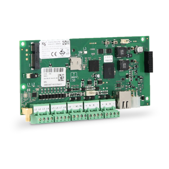
Page 9: Descrizione Scheda Madre Lares 4.0
DESCRIZIONE SCHEDA MADRE lares 4.0 ADD-ON 3G - GSM PULSANTI DI RESET LED STATO L3 DATI DI FABBRICA QR-CODE ADD-ON PSTN TAMPER MICROSWITCH ANTISABOTAGGIO CAVO ETHERNET LED STATO i5 i6 i7 i8 i1 i2 i3 i4 868 MHz ANTENNA KS-BUS KS-BUS ALIMENTAZIONE RED 2014/53/UE... -
Page 10: Morsettiere Di Alimentazione Centrale
Giallo fisso: presenza di problemi di accesso alla memoria NOR. Eseguire la formattazione della centrale. ROSSO FISSO: problema firmware. Contattare l’assistenza tecnica Ksenia. Ripristino a dati di fabbrica: premere il tasto S1 per 4 secondi, il LED L3 lampeggia alternativamente ROSSO-VERDE. -
Page 11: Gsm / 3G
PSTN GSM / 3G Comunicatore GSM / GPRS (Modulo Opzionale) Comunicatore PSTN (Modulo Opzionale) KSI4102000.300 KSI4200001.300 Modulo di espansione PSTN. Comunicatore 3G (Modulo Opzionale) LINE / TEL: terminali di collegamento alla KSI4103000.300 linea telefonica. Cavo antenna GSM / 3G. Modulo di espansione GSM / 3G. Slot Porta SIM Card (micro SIM). -
Page 12: Schema Di Collegamento Del Ks-Bus
SCHEMA DI COLLEGAMENTO DEL KS-BUS (RS485) Tramite il veloce KS-BUS vengono collegate le periferiche del sistema Ksenia. Si consiglia di non superare per ogni ramo filare (centrale - dispositivo) la lunghezza massima di 500m ed un cablaggio completo di 1000m. Usare sempre cavo schermato con un capo dello schermo collegato alla massa della centrale e l’altro lasciato libero. -
Page 13: Configurazione Della Centrale
Per configurare una nuova centrale, premere sul pulsante +, fotografare il QR-code presente sull’etichetta o inserire manualmente il numero di serie a 16 cifre. 2 . La centrale può essere configurata da remoto utilizzando il servizio Ksenia SecureWeb, tramite il portale secureweb, riservato agli Installatori Selezionati Ksenia. -
Page 14: Menu Installatore (Tastiera Su Bus)
MENÙ INSTALLATORE (TASTIERA SU BUS) Nel seguente paragrafo sono descritte le operazioni che possono essere eseguite dalle tastiere su BUS, accedendo al menù installatore tramite codice PIN (DEFAULT 123456). Una volta entrati nel menù installatore è possibile spostarsi tra le varie voci agendo sui tasti: •... -
Page 15: Principali Differenze Rispetto Alla Lares Tradizionale - Guida Rapida
A livello software, la piattaforma lares 4.0 non può essere programmata dal software basis. L’interfaccia installatore di programmazione è realizzata mediante webserver, e quindi la configurazione può essere effettuata tramite app Ksenia PRO, dal portale www.kseniasecureweb.com oppure collegandosi direttamente alla centrale tramite cavo di rete. - Page 16 abbinate agli eventi di Attivazione Uscita e Disattivazione Uscita. • Per ogni uscita è inoltre possibile selezionare diverse modalità di funzionamento nella gestione locale e remota via APP, consentendo ad esempio, una attivazione su rete locale senza PIN e remota con PIN.
-
Page 17: Configurazione Delle Centrali Da Interfaccia Installatore
CONFIGURAZIONE DELLE CENTRALI DA INTERFACCIA INSTALLATORE Che si programmi la centrale da portale www.kseniasecureweb.com, tramite APP mobile Ksenia PRO, o con connessione diretta si accede alla stessa interfaccia di configurazione. Essa si adatta automaticamente alla risoluzione e dimensione dello schermo, sia esso un PC / MAC, tablet o smartphone. -
Page 18: Guida Utente - Operazioni Da Tastiera
GUIDA UTENTE - OPERAZIONI DA TASTIERA LCD ergo Nella seguente sezione sono descritte le operazioni che l’utente finale può eseguire da tastiera LCD. OPERAZIONI DA TASTIERA Per l’uso delle funzionalità dei tasti e dello scroll circolare della tastiera CapSense ergo, fare riferimento al manuale relativo. - Page 19 è necessario inserire un PIN utente valido o avvicinare una chiave programmata alla tastiera ergo. Con questa programmazione, ad impianto disinserito, sulla prima riga della tastiera ergo a riposo, viene visualizzata la stringa ‘AVVISI IN CODA’ o ‘Ksenia Security’ a seconda che ci siano o non ci siano anomalie.
- Page 20 MENÙ PRINCIPALE • Reset allarmi: premendo il tasto Enter si fermano eventuali allarmi in corso e si cancellano le relative memorie. • Stato partizioni: premendo il tasto Enter, è possibile vedere lo stato di inserimento delle partizioni. • Stato zone: premendo il tasto ENTER, è possibile vedere lo stato in tempo reale delle zone. Inoltre è...
- Page 21 Rivolgersi all’installatore del sistema per conoscere le procedure da seguire. Ksenia Security Srl declina ogni responsabilità nel caso in cui le apparecchiature vengano manomesse da personale non autorizzato. Il contenuto di questo manuale può essere soggetto a modifiche, senza preavviso, e non rappresenta...
- Page 22 INDEX INTRODUCTION ..............................23 lares 4.0 HARDWARE - SOFTWARE CHARACTERISTICS ..................23 PARTS IDENTIFICATION ............................24 WALL MOUNTING INSTRUCTION ........................25 MOUNTING NOTES ..............................26 lares 4.0 MOTHERBOARD DESCRIPTION ......................27 CONTROL PANEL POWER TERMINALS .......................28 GSM / 3G ................................29 PSTN ..................................29 KS-BUS CONNECTION DIAGRAM (RS485)......................30 COMPATIBLE BUS DEVICES ..........................30 WIRELESS PERIPHERALS ............................30 CONTROL PANEL CONFIGURATION .........................31...
- Page 23 lares 4.0 represent by far the most advanced and reliable Solution in the Digital Revolution (IoT) for what concern both the Security (Intrusion, Video-surveillance, Access Control) and the Home & Building Automation. The lares 4.0 Platform has been developed and manufactured with unprecedented characteristics of power, calculation speed and capacity of memory calculation.
- Page 24 PARTS IDENTIFICATION Hereafter, shows the main parts composing the lares 4.0 system. The picture also shows the Power Supply connections in detail: pay attention to the protection ground connection. The large buttonhole on the Box bottom provide an wide passage of cables for wiring the peripheral devices also in the case of quite large systems.
- Page 25 WALL MOUNTING INSTRUCTION In order to correctly install the metal cabinet and the components inside it, please follow the instructions here below: 1. Fix the metal box on the wall, using screws Ø6mm (included) 2. Wire the cables as shown in picture. 3.
- Page 26 MOUNTING NOTES Fixing the front cover of the metal box of Control Panel: After closing the cover of the metal box, fix with the included screws at the indicated points: • Arrange outside the Panel an isolating device (es. Circuit Breaker Device 16A Curve C). •...
- Page 27 lares 4.0 MOTHERBOARD DESCRIPTION 3G - GSM ADD-ON RESET BUTTONS L3 STATUS LED FACTORY DATA QR-CODE PSTN ADD-ON TAMPER MICROSWITCH ETHERNET STATUS LED i5 i6 i7 i8 i1 i2 i3 i4 868 MHz ANTENNA KS-BUS KS-BUS POWER SUPPLY RED 2014/53/UE EN50131-3: 2009 EN50131-6: 2008 BATTERY...
- Page 28 Yellow: NOR memory access problems. execute Control Panel formatting. fixed RED: firmware problems. Contact Ksenia Security technical assistance. Factory data restore: press the S1 button for 4 seconds, The status LED L3 will start flashing RED-GREEN color. When the LED L3 turns fixed RED, release the button.
- Page 29 PSTN GSM / 3G GSM / GPRS COMMUNICATOR (Optional Add-on PSTN Communicator (Optional Add-on Module) Module KSI4200001.300 KSI4102000.300 PSTN Communication Module. 3G COMMUNICATOR Optional Add-on Module LINE / TEL: Terminals for wiring to the phone line. KSI4103000.300 GSM / 3G Antenna GSM / 3G Module Slot SIM Card (micro SIM).
- Page 30 KS-BUS CONNECTION DIAGRAM (RS485) Peripheral units of the Ksenia system are connected through the fast KS-BUS. It is recommended not to exceed, for each wiring branch (e.g. Control Panel - device), the maximum length of 500 m (1400 feet), and the complete wiring should not be longer than 1000m (2800 feet). Always use a shielded cable with one end of the shield connected to the Control Panel’s ground and the other end free.
- Page 31 When delivered, the ‘lares 4.0’ Control Panels has to be programmed on purpose. The configuration can be done choosing one of the following modes: 1. remotely, thanks to the APP Ksenia PRO available for iOS and Android. 2. remotely, through the portal: www.kseniasecureweb.com.
- Page 32 INSTALLER MENU (BUS KEYPAD) In this section the keypad installer available operations are described. To access the installer menu the installer code (DEFAULT 123456) is required. The installer menu can be navigated using the following keys: • ENTER: to enter the lower level menu. •...
- Page 33 From the software point of view, the lares 4.0 platform can not be programmed by the basis software. The programming installer interface is realized by webserver, and therefore the configuration can be done via Ksenia PRO APP, from the portal www.kseniasecureweb.com or by connecting directly to the control panel via a network cable.
- Page 34 • Software timers are no longer present, but these have been replaced by virtual outputs, combined with the Output Activation and Output Deactivation events. • For each output it is also possible to select different operating modes in the local or remote management via APP, allowing for example, an activation on local network without PIN and remote with PIN.
- Page 35 CONFIGURATION OF CONTROL PANEL FROM INSTALLER INTERFACE The same configuration interface is available from the portal www.kseniasecureweb.com, via the Ksenia PRO mobile APP, or with direct connection. It automatically adapts to the resolution and screen size, It can be PC / MAC, tablet or smartphone.
- Page 36 USER GUIDE – ergo LCD KEYPAD OPERATIONS In this section the operation available using the ergo LCD KEYPAD are described KEYPAD OPERATIONS Please, see the ergo LCD KEYPAD manual for keys and scroll usage. STAND-BY DISPLAY – UPPER DISPLAY ROW When in stand-by, in the upper display row the system status is shown.
- Page 37 If this is the case, to show these information a valid user PIN or a valid tag must be used. In the upper row the text “Ksenia Security” if everything is ok, or “INFOS AVAILABLE” in other cases will be shown.
- Page 38 MAIN MENU To select an item in the list the ENTER key must be used. • Reset alarm: running alarms will be stopped, and alarm memories cleared. • Partition status: partitions arming status will be displayed. • Zone status: the zones real time status will be displayed; furthermore, using the ENTER key again, the zones will toggle its bypass status.
- Page 39 Test procedures depends on the system configuration. Ask to the installer for the procedures to be followed. Ksenia Security srl shall not be responsible for damage arising from improper installation or maintenance by unauthorized personnel. The content of this guide can change without prior notice from KSENIA...
-
Page 40: Annotazioni
ANNOTAZIONI - NOTES ...................................................................................................................................................................................................................................................................................................................................................................................................................................................................................................................................................................................................................................................................................................................................................................................................................................................................................................................................................................................................................................... - Page 41 ..........................................................................................................................................................................................................................................................................................................................................................................................................................................................................................................................................................................................................................................................................................................................................................................................................................................................................................................................................................................................................................................................................
- Page 44 RISPETTO DELL’AMBIENTE lares 4.0 è stata progettata e realizzata con le seguenti caratteristiche per ridurne l’impatto ambientale: • Plastiche senza PVC • Laminati Halogen-free per circuiti stampati senza piombo • Basso assorbimento • Imballo realizzato per la maggior parte con fibre riciclate e materiali provenienti da fonti rinnovabili Progettata e Realizzata in Italia ENVIROMENTAL CARE lares 4.0...
Need help?
Do you have a question about the lares 4.0 40 and is the answer not in the manual?
Questions and answers