Table of Contents
Advertisement
Advertisement
Table of Contents

Subscribe to Our Youtube Channel
Related Manuals for Ksenia Lares 4.0 wls 96


Summary of Contents for Ksenia Lares 4.0 wls 96
- Page 1 Installation manual www.kseniasecurity.com...
- Page 2 All information in this document is subject to change without notice and does not represent a commitment on the part of Ksenia Security...
-
Page 3: Table Of Contents
4.0 control panel description and connections details 11 Wall mounting instructions 12 lares 4.0 motherboard description 15 lares 4.0 wls 96 control panel description and connections details 16 Local or remote keypad description 17 Wall mounting instruction 18 lares 4.0 wls 96 motherboard description 19... - Page 4 lares 4.0 Installation manual How to read the control panel IP address from keypad 32 lares 4.0 Declaration of conformity 33 lares 4.0 wls Declaration of conformity 34 R30024.120it...
-
Page 5: Introduction
Ksenia Pro installer APP installed any mobile device, by the installer. The Installer APP (Ksenia Pro) allows you to centralize and geolocalize all the installed units and therefore to offer maximum assistance to the end customer by receiving push notifications also for technological alerts. -
Page 6: Main Functions
lares 4.0 Installation manual 1.2 Main functions Hardware Power supply voltage 15 Vcc ± 1% Central Power Consumption (max) 100mA Temperature range +5 °C / +40 °C 23 °F / 131 °F Degree of protection IP IP34 R30024.120en... -
Page 7: Compatibility
KSI1400016.300 - lares 4.0 - 16: up to 16 IN + 16 OUT with 6 partitions - native with Ethernet interface. (no wireless on board - requires a duo transceiver). Dedicated APP for Installer (Ksenia Pro) and User (lares 4.0). •... -
Page 8: Lares 4.0 Wls 96 And Characteristics
• KSI1410096.3xx - lares 4.0 wls 96 Kit (polycarbonate box, power supply and keypad) • KSI1413096.3xx - lares 4.0 wls 96 Kit (polycarbonate box, power supply, keypad and 3G module) • KSI1410096.30x - lares 4.0 wls 96 Kit Able to manage up to 96 overall zonas including 40 wireless and 18 exits. Possible expansion wired on BUS: up to 3... -
Page 9: Technical Data
lares 4.0 Installation manual 1.4 Technical data lares wls 96 40 wls 140 wls 644 wls Power supply voltage 230 V~ -15/+10% 50 Hz 0.4A 230 V~ -15/+10% 50 Hz 0.8A Power Supply Battery Charger (Type A norm EN50131-6) 15V ± 1% 1.7A 15V ±... - Page 10 FULL INSTALLATION CHART Legend KS-BUS 485 Universal PoE / LAN Wireless...
-
Page 11: Installation
lares 4.0 Installation manual 2. INSTALLATION Before starting with the installation, choose an appropriate site where to install the control panel, following the recommendations below: • Choose a vertical flat surface, with sufficient space around for installation and the opening operations. •... -
Page 12: Wall Mounting Instructions
lares 4.0 Installation manual Large slot for passing cables. Removable metal plate. Bottom fixing holes. Support for motherboard. Support for motherboard expansion modules. Tamper micro-switch. 18Ah battery. Cable Included for connecting the Power Supply and the Battery. The two terminals without fastons are for the Power Supply (15Vdc), the two connectors with fastons are for the Battery 12V. - Page 13 lares 4.0 Installation manual - Figure 2 - Removable metal plate - Figure 3 - Metal box fixing holes. If necessary use the included 5 shims box (B). Tamper micro-switch. R30024.120en...
- Page 14 lares 4.0 Installation manual - Figure 4 - Holes for front cover fixing. Use the included 4 screws. Aafter closing the cover of the metal box, fix with the included screws at the indicated points 15. 4. Arrange outside the Panel an isolating device (e.g. Circuit Breaker Device 16A Curve C). 5.
-
Page 15: Lares 4.0 Motherboard Description
lares 4.0 Installation manual 2.1.2 lares 4.0 motherboard description - Figure 5 - Note1: Power Supply cable (n.8 in “- Figure 1 -” page 11 ) included for connecting the Power Supply and the Battery is composed of four terminals: two terminals without fastons are for the Power Supply (15Vdc), the two connectors with fastons are for the Battery 12V. -
Page 16: Lares 4.0 Wls 96 Control Panel Description And Connections Details
4.0 Installation manual 2.2 lares 4.0 wls 96 control panel description and connections details - Figure 6 - To properly install the panel box to the wall, use the Ø 5mm screws (included). GSM Antenna GSM expansion module (optional) -
Page 17: Local Or Remote Keypad Description
lares 4.0 Installation manual Integrate speaker Ethernet Connector QR-code label of control panel Battery Connectors Switch (Reset / Data Factory) Switch (Secureweb Registration) 2.2.1 Local or remote keypad description - Figure 7 - Soft Touch keypad ESC soft touch ENTER key Soft touch Scroll for menu navigation: 4.1 Scroll to Sx 4.2 Scroll Down... -
Page 18: Wall Mounting Instruction
lares 4.0 Installation manual 2.2.2 Wall mounting instruction After removing the 2 fixing screws, open the box front as illustrated below (B): 1. push the plastic clips (A) with a screwdriver; 2. lift outward; 3. slide the cover downwards rotating outwards; - Figure 8 - 4. -
Page 19: Lares 4.0 Wls 96 Motherboard Description
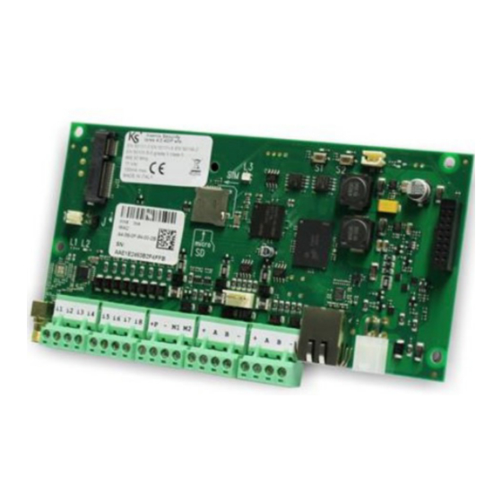
4.0 Installation manual 2.2.3 lares 4.0 wls 96 motherboard description - Figure 10 - Note1: Power Supply cable included for connecting the Power Supply and the Battery is composed of four terminals: two terminals without fastons are for the Power Supply (15Vdc), the two connectors with fastons are for the Battery 12V. -
Page 20: Outputs Section
4.0 Installation manual 2.2.4 Outputs section The motherboard of lares 4.0 wls 96 has 2 OC outputs of 500mA each one, programmable as you need: polarities (normally open or normally closed), functions (bistable or monostable), activation times (ON time). -
Page 21: Maintenance Operations
lares 4.0 Installation manual 2.4 Maintenance operations Factory data restore Press the S1 button for 4 seconds, the status LED L3 will start flashing RED/ GREEN colour. When the LED L3 turns fixed RED, release the button. Sign out from SecureWeb Press the S2 button, the status LED L3 will start flashing GREEN/BLU. -
Page 22: Add-On 3G Module
lares 4.0 Installation manual 2.5 Add-On 3G module 2.5.1 Installation The 3G Add-On is an optional module that is installed on the lares 4.0 motherboard, regardless of the central panel model, in the appropriate "ADD-ON 3G/GSM" slot, shown in the following image. - Figure 12 - ADD-ON 3G module KSI4103000.300... -
Page 23: Add-On 4G/Lte
NOTE2: micro SIM not included in the package. Install 4G/LTE module to enrich lares 4.0 with the following features: • Remote configuration of the control panel through free Ksenia PRO App for installer or from Ksenia SecureWeb service • Remote management of the control panel through free lares 4.0 APP for users •... -
Page 24: Add-On Pstn Module
lares 4.0 Installation manual 2.7 Add-On PSTN module 2.7.1 Installation The PSTN Add-On is an optional module that is installed on the lares 4.0 motherboard, regardless of the central panel model, in the appropriate "ADD-ON PSTN" slot, shown in the following image. - Figure 13 - ADD-ON PSTN module KSI4200001.300... -
Page 25: Control Panel Power Terminals
2.9 KS-BUS (RS485) connection diagram Peripheral units of the Ksenia system are connected through the fast KS-BUS. It is recommended not to exceed, for each wiring branch (control panel - device), the maximum length of 500 m (1400 feet), and the complete wiring should not be longer than 1000m (2800 feet). -
Page 26: Compatible Bus Devices
4.0 Installation manual 2.11 Compatible BUS devices Devices Ksenia product EN50131 Absorption name certified Expansion auxi 20 mA (P terminal and outputs excluded) auxi 10in 20 mA (+P1 and +P2 terminals excluded) auxi relé 100mA max auxi-H 70 mA (P terminal excluded) -
Page 27: Configuration - Logging In For The First Time
“Access to the portal Ksenia SecureWeb” pag. 27 remotely from mobile, downloading the dedicated APP Ksenia PRO for Security installers for free from Android or iOS stores and scanning the control panel’s QR code (how to do it is described in the paragraph “Access to the... -
Page 28: Configuration From Pc
lares 4.0 Installation manual 3.2 Configuration from PC 1. After successful login, www.kseniasecureweb.com page will open; 2. to add a new control panel click on <+> sign in the Panel section, see the following image; 3. type the serial number printed on the control panel label; 4. - Page 29 lares 4.0 Installation manual 6. The following image displays the list of control panels from which the installer can start some operations such as: logging in, editing, deleting, score acquisition, searching by filter, etc. See description below: 1. 2. 3. 5.
-
Page 30: Configuration From App Ksenia Pro
6. click on <Save>. The control panel is ready to be configured by using Ksenia SecureWeb and it will be present in the “devices” list. R30024.120en... -
Page 31: Programming From Keypad
lares 4.0 Installation manual 3.4 Programming from keypad The configuration of the control panel from keypad is limited to a few features listed below. Access the installer menu with a PIN code (default: 123456). You can navigate the various items by pressing the keys once you have entered the installer menu: •... - Page 32 lares 4.0 Installation manual 3.4.1 How to read the control panel IP address from keypad If the network, where the control panel is installed, supports DHCP, to read the IP address make the following operations: • Step 1. make sure the control panel is connected to the network; •...
- Page 33 3.5 lares 4.0 Declaration of conformity DICHIARAZIONE DI CONFORMITÀ UE UE DECLARATION OF CONFORMITY DÉCLARATION DE CONFORMITÉ UE Ksenia Security Srl, Strada Provinciale Valtesino, 44 – 63065 Ripatransone AP - Italia Dichiara che / Declares that / Déclare que: lares 4.0 KSI1400016.300 centrale lares 4.0 - 16 / Control Panel lares 4.0 - 16 /...
- Page 34 3.6 lares 4.0 wls Declaration of conformity DICHIARAZIONE DI CONFORMITÀ UE UE DECLARATION OF CONFORMITY DÉCLARATION DE CONFORMITÉ UE Ksenia Security Srl, Strada Provinciale Valtesino, 44 – 63065 Ripatransone AP - Italia Dichiara che / Declares that / Déclare que: lares 4.0 wls KSI1410040.300 Centrale / Control Panel / centrale d’alarme lares 4.0 - 40wls...
- Page 35 Ksenia Security srl shall not be responsible for damage arising from improper installation or maintenance by unauthorized personnel. The content of this guide can change without prior notice from KSENIA SECURITY and does not represent a commitment on the part of Ksenia Security.
- Page 36 PETTO DELL'AMBIENTE ENVIROMENTAL CARE lares 4.0 is designed and manufactured with the following features to reduce its environmental impact: • No PVC • Halogen-free laminates and lead-free PCBA • Low consumption • Packaging realized mainly with recycled fibers and materialsl Designed and Produced in Italy code R30024.120en ed.07/2020...
Need help?
Do you have a question about the Lares 4.0 wls 96 and is the answer not in the manual?
Questions and answers