
Related Manuals for Allen-Bradley CENTERLINE 1500


Summary of Contents for Allen-Bradley CENTERLINE 1500
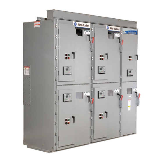
- Page 1 User Manual Original Instructions CENTERLINE 600 A One-High Cabinet, Standard and Arc-Resistant Enclosure Bulletin Numbers 1512A, 1512AT, 1512DM, 1512DO, 1512M, 1562E, 1912B, 1912L...
- Page 2 Important User Information Read this document and the documents listed in the additional resources section about installation, configuration, and operation of this equipment before you install, configure, operate, or maintain this product. Users are required to familiarize themselves with installation and wiring instructions in addition to requirements of all applicable codes, laws, and standards.
-
Page 3: Table Of Contents
Table of Contents Preface About This Publication ......... 7 What This Manual Contains. - Page 4 Table of Contents Hi-Pot and Insulation Resistance Test ......43 Start-up Procedure ..........43 Contactor Inspection .
- Page 5 Table of Contents Appendix B ArcShield Plenum Installation Recommended Torque Values........79 Plenum Bracing .
- Page 6 Table of Contents Notes: Rockwell Automation Publication 1512A-UM101A-EN-P - October 2018...
-
Page 7: Preface
CENTERLINE 1500 motor control center. If you do not have a basic understanding of the CENTERLINE 1500 motor control center, contact your local Allen-Bradley distributor or Rockwell Automation sales representative for information on available training courses... - Page 8 Preface Notes: Rockwell Automation Publication 1512A-UM101A-EN-P - October 2018...
-
Page 9: Starter Identification
Chapter General Information This manual pertains to the CENTERLINE® 1500, 600 A medium voltage motor control center. This MCC structure provides one complete medium voltage controller unit. The installation section provides instructions for both the standard enclosure type and the arc resistant structure type (ArcShield™). The product Bulletin numbers that are primarily covered by this document are: •... - Page 10 Chapter 1 General Information Figure 1 - Typical Structure Nameplate A nameplate is also found in the low voltage compartment (see Figure 2) with specific unit motor application information. Figure 2 - Typical Unit Nameplate See these nameplates whenever you contact Rockwell Automation for assistance.
-
Page 11: Recommended Torque Values
General Information Chapter 1 Recommended Torque When reinstalling components, or when reassembling the cabinet, tighten the following bolt sizes to the specified torque values: Values Table 1 - Torque Values for Hardware 1/4 in. hardware 8 N•m (6 lb•ft) 5/16 in. hardware 15 N•m (12 lb•ft) 3/8 in. -
Page 12: High Altitude Application
Chapter 1 General Information High Altitude Application The equipment operates at altitudes from 0…1000 m (0…3300 ft) above sea level, without derating. For applications above 1000 m (3300 ft), the maximum current and basic impulse levels (BIL) of the controllers shall be derated, and vacuum contactors may be compensated for operation at the specified altitude (see publication 1500-SR020). -
Page 13: Door Opening Procedure
Chapter Installation – Standard Enclosure IMPORTANT For information on the installation site preparation, see publication MV-QS050. ATTENTION: Use suitable personal protective equipment (PPE) per local codes or regulations. Failure to do so may result in severe burns, injury, or death. Refer to the standards such as NFPA 70E, Standard for Electrical Safety in the Workplace and CSA Z462, Workplace Electrical Safety Standard for safety guidance when working in and around electrical equipment. -
Page 14: Opening The Medium Voltage Doors
Chapter 2 Installation – Standard Enclosure Refer to Access to the Power Bus on page 18 for the procedure to open the swing-out low voltage panel behind the low voltage door. ATTENTION: Medium voltage components may be located behind the swing-out low voltage panel (standard cabinets only). -
Page 15: Anchoring
Installation – Standard Enclosure Chapter 2 4. The doors are now released and will swing open to the left. 5. Reverse the procedure to close the door IMPORTANT Verify that the swing-out low voltage panel is in its original position before attempting to close the MV door. - Page 16 Chapter 2 Installation – Standard Enclosure Figure 5 - Standard Top Entry/Exit Locations • A - Line Cable Conduit Opening 0 [0] 5.68 x 9.00 [144 x 229] • B - Load Cable Conduit Opening 4.65 [118] 9.00 x 10.00 [229 x 242] •...
-
Page 17: Joining Sections
Installation – Standard Enclosure Chapter 2 Joining Sections TIP Joining hardware can be found in a package that is mounted to the front of the shipping skid. See publication MV-QS050 for level floor surface requirements. IMPORTANT For arc resistant cabinets, see Chapter 3 for special instructions. -
Page 18: Access To The Power Bus
Chapter 2 Installation – Standard Enclosure Figure 7 - Joining Sections Side Bus Access Cover 0.281 Pilot 0.219 Pilot Holes (5x) Holes (5x) 0.219 Pilot Holes (3x) 0.281 Pilot Holes (5x) Access to the Power Bus ATTENTION: This procedure requires contact with medium voltage components. -
Page 19: Side Access
Installation – Standard Enclosure Chapter 2 Figure 8 - Access to Power Bus from Side and Rear of Cabinet Center Rear Bus Access Cover Side Bus Access Cover Figure 9 - Rear Power Bus Access, Rear Panel Removed Side Access A side bus access cover is on each side of the controller. -
Page 20: Front Access - Top Incoming Line Cables And Power Bus
Chapter 2 Installation – Standard Enclosure Figure 10 - Side Power Bus Access, Right Side Access Panel Removed Front Access – Top Incoming Line Cables and Power Bus Complete the Power Lockout Procedure (See Power Lock-out Procedure on page 49) for both medium voltage power cells and the power bus. 1. - Page 21 Installation – Standard Enclosure Chapter 2 Figure 11 - Low Voltage Panel Remove self-tapping screws from center vertical channel 6. Remove two self-tapping screws from the lower low voltage panel upright supports (Figure 12). 7. Pull on right-hand side of low voltage panel. Swing low voltage panel to the front and left of cabinet TIP The power MV cell doors must be removed before rotating the low voltage panel.
- Page 22 Chapter 2 Installation – Standard Enclosure Figure 12 - Low Voltage Panel, Lower Remove self-tapping screws from center vertical channel 8. Locate the removable bus access barriers (Figure 13). Figure 13 - Power Bus Barriers Remove These Panels For Access To Power Bus Rockwell Automation Publication 1512A-UM101A-EN-P - October 2018...
-
Page 23: Front Access - Bottom Incoming Line Cables
Installation – Standard Enclosure Chapter 2 ATTENTION: Confirm all barriers are replaced before re-energizing the equipment. Failure to do so may result in electrical faults and can cause damage to equipment or severe injury to personnel. 9. Remove retaining screws from removable bus access barriers to expose incoming cable connections to main bus (see Figure 13). -
Page 24: Load Cable Connections
Chapter 2 Installation – Standard Enclosure Figure 14 - Access to Bottom Incoming Line Cables Bottom incoming cable duct in power cell Cable duct access barrier ATTENTION: Ensure all barriers are replaced before re-energizing the equipment. Failure to do so may result in electrical faults and can cause damage to equipment or severe injury to personnel. - Page 25 Installation – Standard Enclosure Chapter 2 3. Load cables for the power cell should be routed before control cables. Pull the cables into the cabinet through the appropriate opening (see Figure 15 Figure 16). 4. Remove the front current transformer barrier. 5.
- Page 26 Chapter 2 Installation – Standard Enclosure Figure 16 - Load Cable Conduit Openings, Top Exit Load Cable Conduit Opening For Cables From Top Power Cell Ground Lug Rockwell Automation Publication 1512A-UM101A-EN-P - October 2018...
-
Page 27: Door Opening Procedure
Chapter Installation – Arc-Resistant (ArcShield) This installation section contains information that is related only to the Rockwell Automation arc resistant enclosures, referred to as ArcShield™. IMPORTANT For information on the installation site preparation, see publication MV-QS050. ATTENTION: Use suitable personal protective equipment (PPE) per local codes or regulations. -
Page 28: Opening The Medium Voltage Door
Chapter 3 Installation – Arc-Resistant (ArcShield) ATTENTION: Complete the Power Lockout procedure (See Power Lock-out Procedure on page 49) before beginning any service procedures to the unit. Failure to do so may result in severe burns, injury, or death. Opening the Medium Voltage Door Figure 18 - Access to Medium Voltage Compartments IMPORTANT The medium voltage door has its own isolation switch handle and interlocking safeguards. -
Page 29: Anchoring
Installation – Arc-Resistant (ArcShield) Chapter 3 Figure 19 - Label on Arc Resistant Door IMPORTANT The last step in closing the medium voltage door, ensure all door locking bolts on the right side of the MV door are in place and tightened until the door is flush with the flange. - Page 30 Chapter 3 Installation – Arc-Resistant (ArcShield) IMPORTANT Pre-determined cabinets have been designed for Uniform Building Code (UBC) seismic zone 1, 2A, 2B, 3 and 4, and IBC (International Building Code) seismic activity without overturning or lateral movement, provided they are securely mounted according to UBC, IBC, and local building codes.
-
Page 31: Joining Sections
Installation – Arc-Resistant (ArcShield) Chapter 3 SEISMIC APPLICATIONS • For installation on concrete – the minimum depth and radius of concrete supporting the cabinet anchors is dependent on seismic loads. Refer to important information above. • For installation on a metal structure – the metal plate depth and cabinet anchoring method is dependent on seismic loads. -
Page 32: Access To The Power Bus
Chapter 3 Installation – Arc-Resistant (ArcShield) Figure 22 - Joining Sections Power Bus cutout holes must align Silicone is applied around power bus cutout area to prevent gas leakage between joined cabinets Access to the Power Bus ATTENTION: This procedure requires contact with medium voltage components. -
Page 33: Side Access
Installation – Arc-Resistant (ArcShield) Chapter 3 Figure 23 - Access to Power Bus from Side and Rear of Cabinet Side Bus Access Cover Center Rear Bus Access Cover Side Access A side bus access cover is on each side of the controller, when required. 1. -
Page 34: Front Access To Power Bus (Bottom Entry/Exit)
Chapter 3 Installation – Arc-Resistant (ArcShield) Figure 25 - Side Bus Access Cover Ground Connection (Rear Access Cover removed to show connection point) Side Bus Access Cover Ground Connection Figure 26 - ArcShield Ground Plate Removable Handle Front Access to Power Bus (Bottom Entry/Exit) 1. -
Page 35: Front Access - Top Incoming Line Cables (Top Entry/Exit)
Installation – Arc-Resistant (ArcShield) Chapter 3 Figure 27 - Removal of Access Panel with Low Voltage Panel Rotated Power Bus Front Access Panels 4. Remove the bolts that secure the access panel to the frame – remove the panels (Figure 27). -
Page 36: Load Cable Connections
Chapter 3 Installation – Arc-Resistant (ArcShield) 5. Install incoming line cables to power bus. Torque to specifications (See Recommended Torque Values on page 11). 6. Reverse procedure after cables have been installed. Load Cable Connections ATTENTION: To avoid shock hazards, lock out incoming power (See Power Lock-out Procedure on page 49) before working on the equipment. - Page 37 Installation – Arc-Resistant (ArcShield) Chapter 3 Figure 28 - Load Cable Conduit Openings (Top Exit Cable Configuration Shown) Load Cable Conduit Opening For Cables From Top Power Cell Ground Lug Figure 29 - Load Cable Conduit Openings (Bottom Exit Cable Configuration Shown) Rockwell Automation Publication 1512A-UM101A-EN-P - October 2018...
- Page 38 Chapter 3 Installation – Arc-Resistant (ArcShield) Notes: Rockwell Automation Publication 1512A-UM101A-EN-P - October 2018...
-
Page 39: Bus Splicing
Chapter Common Installation Bus Splicing Power Bus ATTENTION: This procedure requires contact with medium voltage components. To avoid shock hazards, lock out incoming power before working on the equipment (See Power Lock-out Procedure on page 49). Verify with a hot stick or appropriate voltage measuring device that all circuits are voltage free. -
Page 40: Insulated Power Bus Splicing
Chapter 4 Common Installation Figure 30 - Typical 1200 A Power Bus Splicing Configuration (Viewed from front of cabinet) Bus Support Bus Clamp Power Bus Splice Bar Main Horizontal Flat Washer Power Bus Hex Nut Lock Washer Figure 31 - Typical 2000 A Power Bus Splicing Configuration (Viewed from front of cabinet) Bus Support Bus Clamp Power Bus... -
Page 41: Ground Bus
Common Installation Chapter 4 Ground Bus 1. See Figure 32 to determine the correct ground splice configuration and assemble as shown. 2. Torque the hardware to 15 N•m ± 1 N•m (12 lb•ft ± 1 lb•ft). 3. Check all hardware for correct tightness and replace all covers and plates. -
Page 42: Incoming Line Cable Connections
Chapter 4 Common Installation Incoming Line Cable ATTENTION: To avoid shock hazards, lock out incoming power (See Power Connections Lock-out Procedure on page 49) before working on the equipment. Verify with a hot stick or appropriate voltage measuring device that all circuits are voltage free. -
Page 43: Hi-Pot And Insulation Resistance Test
Common Installation Chapter 4 Hi-Pot and Insulation Insulation integrity should be checked before energizing medium voltage electrical equipment. Use a high voltage AC insulation tester (5000V) for this Resistance Test test. ATTENTION: Exercise caution when performing high voltage tests on the equipment. -
Page 44: Testing Contactor Operation
Chapter 4 Common Installation • All barriers are replaced to correct positions; • All fuses are correct class, type and rating; • Mechanical interlocks and isolation switch function properly; • Verify that any microprocessor-based protection relay is programmed; • Interior of cabinet is free from dirt, loose bolts, tools, or metal chips. Vacuum clean if necessary;... - Page 45 Common Installation Chapter 4 Figure 34 - Typical Wiring Diagram: Electrically Held Vacuum Contactor (with IntelliVAC Control) Rockwell Automation Publication 1512A-UM101A-EN-P - October 2018...
- Page 46 Chapter 4 Common Installation Figure 35 - Typical Wiring Diagram: Electrically Held Vacuum Contactor (Relay Control) Rockwell Automation Publication 1512A-UM101A-EN-P - October 2018...
-
Page 47: Maintenance
Chapter Maintenance ATTENTION: Use suitable personal protective equipment (PPE) per local codes or regulations. Failure to do so may result in severe burns, injury, or death. IMPORTANT Establish a maintenance and inspection schedule for the equipment. Annual servicing, or every 20,000 operations (whichever comes sooner) are the minimum recommended. -
Page 48: Door Interlock Circumvention
Chapter 5 Maintenance Door Interlock ATTENTION: The door interlock mechanism is designed to prevent access to Circumvention the medium voltage cell while the unit is energized. When the unit is in operation, do not circumvent this interlocking safety feature. Always disconnect and lock out incoming power (refer to Power Lock-out Procedure on page... -
Page 49: Power Lock-Out Procedure
Maintenance Chapter 5 Power Lock-out Procedure ATTENTION: Use suitable personal protective equipment (PPE) per local codes or regulations. Failure to do so may result in severe burns, injury, or death. ATTENTION: Always perform the power lockout procedure before servicing the equipment. Failure to do so may result in severe burns, injury, or death. ATTENTION: The following procedure requires moving the isolation switch handle to the ON position. - Page 50 Chapter 5 Maintenance Figure 37 - Typical Contactor Control Panel (IntelliVAC™ Control) Control Switch Auxiliary Power Receptacle 4. Open the medium voltage door. 5. Visually inspect that the isolation switch blades fully engage the grounding pins on the grounding bar. The isolation switch shutters should be closed (see Figure 38).
- Page 51 Maintenance Chapter 5 Figure 38 - Inspecting Isolation Switch in Open Position See Detail A Grounding Bar Isolation Switch Blades must fully engage Grounding Pins of Grounding bar (Verify for each phase) Isolation Switch Shutters must be closed (Verify for each phase) Grounding Pins Detail A Isolation Switch...
- Page 52 Chapter 5 Maintenance Figure 39 - Contactor Voltage Checkpoints Line Side Load Side 7. Use the Door Interlock Circumvention procedure (refer to Door Interlock Circumvention on page 48) to move the isolation switch handle to the ON position. 8. Check the isolation switch blades with a hot stick or appropriate voltage measuring device to verify that they are voltage free (see Figure 40).
-
Page 53: Fuse Removal And Replacement
Maintenance Chapter 5 Fuse Removal and Replacement ATTENTION: Only personnel who have been trained and understand the Bulletin 1500 product line are to work on this equipment. Suitable safety equipment and procedures must be used always. ATTENTION: Servicing energized industrial control equipment can be hazardous. -
Page 54: Clip-On Fuse Removal/Installation
Chapter 5 Maintenance 4. Install the lower two flat washers, lock washers and nuts. Torque nuts to 15 N•m (12 lb•ft). 5. If interphase barriers were previously removed ensure they are properly reinstalled. Figure 41 - Medium Voltage Power Fuses Bolt-on Fuses Clip-on Fuse Optional Clip-on Fuse Extractor... -
Page 55: Contactor Maintenance
Maintenance Chapter 5 4. Remove the lower portion of the fuse from fuse clip by pulling up and slightly rotating the fuse in one entire movement. 5. To install the replacement fuse, place the fuse between the fuse clips. 6. Ensure that the flares on the fuse ferrules are properly located with regard to the fuse clips. -
Page 56: Remove The Contactor
Chapter 5 Maintenance Remove the Contactor ATTENTION: To avoid shock hazards, lock out incoming power (refer to Power Lock-out Procedure on page 49) before working on the equipment. Verify with a hot stick or appropriate voltage measuring device that all circuits are voltage free. - Page 57 Maintenance Chapter 5 Figure 44 - Removing the Contactor Contactor Interlock Rod Nylon Contactor Bushing Retaining Screw Nylon Contactor Bushing Contactor Interlock Lever 7. Remove the two contactor mounting bolts at the front of the contactor. 8. Slide the contactor forward slightly to disengage the retaining tabs at the rear of the contactor from the mounting bracket inside the cabinet.
-
Page 58: Contactor Interlock Rod Adjustment
Chapter 5 Maintenance Contactor Interlock Rod ATTENTION: To avoid shock hazards, lock out incoming power (refer Adjustment Power Lock-out Procedure on page 49) before working on the equipment. Verify with a hot stick or appropriate voltage measuring device that all circuits are voltage free. -
Page 59: To Reduce The Gap Distance
Maintenance Chapter 5 To Reduce the Gap Distance 1. Loosen the two screws in the stop bracket and move the stop bracket up against the interlock lever. 2. With the feeler gauge positioned in the gap, move the interlock lever and the stop bracket closer to the isolation switch operating lever to reduce the gap space. -
Page 60: Isolation Switch Mechanism Inspection And Lubrication
Chapter 5 Maintenance 7. Open the contactor. Verify that the interlock lever and the rod move freely and that the return springs move the assembly back to the starting position. Isolation Switch Mechanism ATTENTION: To avoid shock hazards, lock out incoming power (refer to Power Inspection and Lubrication Lock-out Procedure on page... -
Page 61: Isolation Blade Switch Adjustment
Maintenance Chapter 5 7. Remove any dirt and dried grease. IMPORTANT Do not scrape or file the parts. This may remove the plating and expose the underlying copper to corrosion. 8. Lubricate in between isolation switch blades and the isolation switch blade pivot points with Nyogel 759G (see Figure 48). - Page 62 Chapter 5 Maintenance Figure 49 - Isolation Switch Defeater Closed position Isolation Switch Operating Handle Isolation Switch Defeater Open position 3. Phase 3 (far right linkage) must be measured for overall travel. All three phases share the same main actuating shaft but the Phase 3 is the easiest to measure.
- Page 63 Maintenance Chapter 5 Figure 51 - Isolation Switch Linkage Assembly Angle Location Must have tolerance of Shaft Assembly 0/+6º Red Glass Polyester Switch Link 5. Loosen the lock nuts at each clevis (Note: one is a left-handed thread). 6. Adjust the isolation switch mechanical threaded linkage with a wrench until the overall travel angle of the switch link is within the required tolerance.
-
Page 64: Isolation Switch Mechanism Grounding Adjustment
Chapter 5 Maintenance 8. Actuate the Isolation Switch handle to verify the travel angle. If the angle is incorrect, repeat steps 5…7 until desired travel angle is reached. ATTENTION: All three isolation switch linkage assemblies must meet the angle tolerance requirements. Isolation Switch Mechanism ATTENTION: To avoid shock hazards, lock out incoming power (refer Grounding Adjustment... -
Page 65: Auxiliary Contacts Inspection And Replacement
Maintenance Chapter 5 2. To adjust the distance from the blades to the bar, disconnect the threaded connecting rod at the handle operating lever. 3. Turn the threaded connecting rod to lengthen or shorten it. This will adjust the position of the isolation switch blades in the ON and OFF position. -
Page 66: Adjusting The Normally Open (Isa) Contacts
Chapter 5 Maintenance Figure 55 - Location of ISa and ISb Auxiliary Contacts ISa Auxiliary ISb Auxiliary Contacts (N.C.) Contacts (N.O.) ISa and ISb contacts are exactly the same (700 CPM). The cam controls the normally open or normally closed status of the contacts. Refer to Figure 34 on page 45 Figure 35 on page 46... -
Page 67: Adjusting The Normally Closed (Isb) Contacts
Maintenance Chapter 5 Figure 56 - Adjusting Auxiliary Contacts, left side view (ISa Auxiliary Contact Shown) Gap: 0.25 in. (6.35 mm) Cam Follower Auxiliary Contact 5. Adjust the cam on the shaft so that the gap from the cam follower to the end of the cam groove is the width of the pin —... -
Page 68: Adjusting The Change-Of-State Point
Chapter 5 Maintenance 7. Verify that auxiliary contact ISb is closed when isolation switch is open. Verify that ISb contact is open when isolation switch is closed. Adjusting the Change-of-State Point This procedure sets the secondary electrical interlock. When properly adjusted, the electrical interlock is designed to open the control power circuit before the isolation switch opens as the handle is moved to the OFF position. - Page 69 Maintenance Chapter 5 Figure 57 - Z-clip Assembly Handle Pin Remove 1/4-20 self-tapping screws Remove Z-clip 2. Loosen the two door locking bolts. 3. Use a flat-headed screwdriver to turn the defeater pin on the right side of the isolation switch handle. Figure 58 - Defeater Pin Defeater Pin 4.
-
Page 70: Off Position
Chapter 5 Maintenance If it is not possible to move the isolation switch handle to the OFF position for reassembly, follow steps 11…14. ATTENTION: The Z-clip assembly must be reassembled to ensure the interlocking mechanism functions properly. Failure to do so will let personnel access live medium voltage parts and may cause severe burns, injury or death. -
Page 71: Spare Parts
Chapter Spare Parts Spare Parts List The spare parts in Table 3 are typical for all Bulletin 1512A units. Other catalog numbered units, referenced in this manual, may require additional spare parts depending on their use or application. Contact your local Rockwell Automation office to ensure that these part numbers are valid for your system. - Page 72 Chapter 1 Spare Parts Notes: Rockwell Automation Publication 1512A-UM101A-EN-P - October 2018...
-
Page 73: Arcshield Unit Information
Appendix ArcShield Unit Information Overview ArcShield™ units have a robust arc resistant enclosure design that has been tested per IEEE C37.20.7 (2001). Each ArcShield structure was tested to withstand the effects of an arc flash at 40 kA or 50 kA for 0.5 seconds. ArcShield units provide an enhanced Type 2B accessibility level. -
Page 74: Arcshield Design
Appendix A ArcShield Unit Information ArcShield Design ArcShield units typically include a pressure relief vent on the roof of the structure (some incoming units may not have a pressure relief vent if top cable entry is required). Under arc flash conditions the pressure relief vent will open allowing hazardous flames and gases to exit the enclosure via plenum or chimney system. -
Page 75: Plenum Exhaust Considerations
ArcShield Unit Information Appendix A Figure 60 - Cross-section of Plenum Extension, dimensions in inches [mm] 23 [584] 25 [633] Plenum Exhaust Considerations The following options for locating the plenum exhaust are presented: 1. Plenum ducted to an area of the control room where arc gases are permitted to escape, with plenum extensions (see Figure Figure... - Page 76 Appendix A ArcShield Unit Information Figure 61 - Plenum Exit Left with Extensions to Internal Controlled Access Area (Top View) Personnel Access Barrier Figure 62 - Plenum Exit Left with Extension(s) to Internal Controlled Access Area (Front View) Personnel Access Barrier Minimum H = 3.5 m (138 in.) Minimum L = 1.2 m (47 in.) Minimum Volume of space required for safe pressure relief: X * Y * H = 11 m...
-
Page 77: Additional Notes
ArcShield Unit Information Appendix A Figure 63 - Chimney Exhaust Space Requirements Chimney Exhaust Considerations on page • Minimum H1: 1.7 m (67 in.) • Minimum H: 1 m (39 in.) Additional Notes • The walls of the plenum exit area must be capable of withstanding the pressure generated. -
Page 78: Chimney Information
Appendix A ArcShield Unit Information Chimney Information Where adequate clean height (space) is available, chimney can be provided for each unit in place of the plenum system. It is to be field mounted on top of the unit structure. The purpose of the chimney is to direct the hazardous flames and gases away from the top of the resistant enclosure. -
Page 79: Recommended Torque Values
Appendix ArcShield Plenum Installation Instructions These instructions are provided to ensure the proper installation and function of plenum components supplied with ArcShield enclosures. See Appendix A for additional information related to ArcShield plenums before attempting to follow these instructions. Recommended Torque 1/4-20 Thread Fasteners –... - Page 80 Appendix B ArcShield Plenum Installation Instructions Figure 64 - Plenum Exhaust Label DANGER DANGER ARC FLASH HAZARD HAZARD D’ARC ÉLECTRIQUE PRESSURE RELIEF EXIT SORTIE DE L’ÉVENT RÉGION ÊTRE: AREAS TO BE: - INACCESSIBLE AUX PERSONNEL - INACCESSIBLE TO PERSONNEL PENDANT QUE L’ÉQUIPEMENT WHILE EQUIPMENT ENERGIZED.
-
Page 81: General Plenum Layout For Arcshield Line-Up
ArcShield Plenum Installation Instructions Appendix B General Plenum Layout for An example of a general Plenum assembly configuration is shown in Figure Plenums of different widths are mounted directly over the MV enclosures of ArcShield Line-up the corresponding width. A 0.9 m (36 in.) Exhaust extension assembly is shown mounted on the extreme right side Plenum of the equipment “Line-up”... -
Page 82: Cabinet Preparation
Appendix B ArcShield Plenum Installation Instructions Figure 67 - Removing Front Duct Section Front Duct Section Components Cabinet Preparation In preparation for mounting plenum, the cabinet lifting means (slips of lifting angles) must be removed. The bolts retaining the lifting means must be replaced in the holes from where they came (Figure 68). -
Page 83: Plenum Placement On Structure
ArcShield Plenum Installation Instructions Appendix B Figure 68 - Typical Relief Vent Fasteners (top view) Figure 69 - Relief Vent Relief vent Corner Fasteners - DO NOT REMOVE Relief fasteners Lifting Angle Hardware Location The plenums are designed to fit over the fastener heads at the four corners of the relief vent. -
Page 84: Step 2 - Alignment Of Side By Side Plenums
Appendix B ArcShield Plenum Installation Instructions Figure 70 - Plenum Placement Use recommended torque value for 1/4-20 fasteners TIP Use silicone caulking generously to fill any air gaps once the Plenum has been securely mounted in place. STEP 2 – Alignment of Side Plenums that are mounted side by side must be fastened together through the aligning holes using 5/16 in. -
Page 85: Step 3 - Sequence Of Final Assembly
ArcShield Plenum Installation Instructions Appendix B Figure 71 - Aligning Side by Side Plenums IMPORTANT Any unused holes must be filled with thread-forming screws. All gaps must be sealed and filled with silicone. All plenums in a Line-up must be mounted to the top of each enclosure and to STEP 3 –... -
Page 86: Step 4 - Closing The Front Of The Plenum Sections
Appendix B ArcShield Plenum Installation Instructions The End Cover Plate must be mounted on the closed end of the line-up during the assembly using 5/16 in. hardware (see Figure 72 left side). STEP 4 – Closing the Front of After the first stage of the plenum assemblies have been mounted, they can then be “closed-up”... -
Page 87: Step 6 - Mounting Extension/Elbow To Plenum Line-Up
ArcShield Plenum Installation Instructions Appendix B Figure 74 - 90° Elbow Section Assembly, Step 5A (Front View) Figure 75 - 90° Elbow Section Assembly, Step 5B (Front View) 36 in. extensions Screen Cover Plate ° 2-piece 90 elbow section Figure 76 - 90° Elbow Section Assembly, Step 5C (Front View) The Extension components are attached to the Elbow Section using 5/16 in. - Page 88 Appendix B ArcShield Plenum Installation Instructions Figure 77 - Optional Extension/Elbow with Vertical Extension (Right side exit) Last Plenum in line-up remains open for installation of extension assembly After the extension/elbow assembly is attached through the fastener holes on the inside flange of the plenum, the front duct section can be replaced and fastened through the holes on the outside flanges.
-
Page 89: Step 7 - Additional Mounting Support
ArcShield Plenum Installation Instructions Appendix B STEP 7 – Additional The extension/elbow assembly must have additional mounting support. Mounting Support 90° Elbow Section: Approximate weight 64 kg (142 lb) 36 in. Extension Assembly: Approximate weight 51 kg (112 lb) Figure 78 shows an example of how the extension/elbow sections can be supported by suspension from a high ceiling. - Page 90 Appendix B ArcShield Plenum Installation Instructions Notes: Rockwell Automation Publication 1512A-UM101A-EN-P - October 2018...
-
Page 91: Recommended Torque Values
Appendix ArcShield Chimney Installation Instructions The following instructions are provided to ensure the proper installation and function of chimney supplied with ArcShield™ enclosures. Refer to Appendix A for additional information related to ArcShield chimney before attempting to follow these instructions. Recommended Torque 1 /4 -20 Thread Fasteners —... -
Page 92: General Plenum Layout For Arcshield Line-Up
Appendix C ArcShield Chimney Installation Instructions General Plenum Layout for An example of a general chimney assembly configuration is shown in Figure 81. Plenums of varying widths are mounted directly over the MV ArcShield Line-up enclosures of the corresponding width. Figure 80 - Typical ArcShield Line-up with Chimney Arc Gas Ducting Rockwell Automation Publication 1512A-UM101A-EN-P - October 2018... -
Page 93: Cabinet Preparation
ArcShield Chimney Installation Instructions Appendix C Cabinet Preparation In preparation for mounting a chimney, the cabinet lifting means (slips of lifting angles) must be removed. The bolts retaining the lifting means must be replaced in the holes from where they came (Figure 81). -
Page 94: Chimney Placement On Structure
Appendix C ArcShield Chimney Installation Instructions Chimney Placement on Structure Once the chimney has been lifted in place directly over the relief vent (Figure 82), all 1/4-20 fasteners, removed in Cabinet Preparation, are replaced to attach the chimney to the top of the enclosure. Figure 83 - Chimney Placement Use recommended torque value for 1/4-20 fasteners... -
Page 95: Index
Index contactor inspection 43 access barrier 76 interlock rod adjustment 58 access cover maintenance 55 rear bus 19 removal 56 side bus 19 test operation 44 additional resources 7 voltage checkpoints 52 altitude 12 ambient temperature 11 anchoring 15 defeater arc resistant 29 location 62 arc resistant cabinet... - Page 96 Index interlock adjustment rod 58 plenum 74 interlock lever 57 access barrier 76 bracing 79 international building code 15 cabinet preparation 82 ISa contact 66 closing sections 86 adjust 67 components 80 ISb contact 66 cross-section 75 adjust 67 end cover plate 85 isolation switch exhaust considerations 75 blade adjustment 61...
- Page 97 Index starter identification 9 start-up 43 storage 11 torque values 11 chimney 91 plenum 79 typical wiring diagrams 45 UBC 15 uniform building code 15 wiring diagrams 45 z-clip installation 70 Rockwell Automation Publication 1512A-UM101A-EN-P - October 2018...
- Page 98 Index Notes: Rockwell Automation Publication 1512A-UM101A-EN-P - October 2018...
- Page 100 How Are We Doing? form at http://literature.rockwellautomation.com/idc/groups/literature/documents/du/ra-du002_-en-e.pdf. Rockwell Automation maintains current product environmental information on its website at http://www.rockwellautomation.com/rockwellautomation/about-us/sustainability-ethics/product-environmental-compliance.page. Allen-Bradley, ArcShield, CENTERLINE, IntelliVAC, Rockwell Automation, and Rockwell Software are trademarks of Rockwell Automation, Inc. Trademarks not belonging to Rockwell Automation are property of their respective companies.
Need help?
Do you have a question about the CENTERLINE 1500 and is the answer not in the manual?
Questions and answers