Advertisement
Advertisement
Table of Contents

Related Manuals for Iveco Motors N67 MNT M28


Summary of Contents for Iveco Motors N67 MNT M28
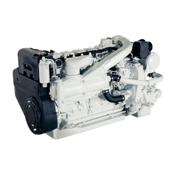
- Page 1 NEF E NGINE N67 MNT M28 ECHNICAL AND EPAIR ANUAL OCTOBER 2005 EDITION...
- Page 2 The indications contained in this document pertain to the N67 MNT M28 marine engine and complement the IVECO MOTORS publication of “Marine Diesel Engines Installation Handbook” that the reader should refer to for anything that is not explained herein.
- Page 3 OCTOBER 2005 N67 MNT M28 SECTION CONTENTS Section Page 1. OVERVIEW 2. TECHNICAL DATA 3. ELECTRICAL EQUIPMENT 4. DIAGNOSTICS 5. MAINTENANCE 6. SERVICING OPERATIONS ON INSTALLED ENGINE 7. TOOLS 8. OVERHAUL 9. SAFETY REGULATIONS Indications for consultation Sections 1-2-3 are intended for sales personnel, to provide them with exact knowledge of the product’s characteri-...
- Page 4 N67 MNT M28 OCTOBER 2005...
-
Page 5: Table Of Contents
OCTOBER 2005 OVERVIEW N67 MNT M28 SECTION 1 OVERVIEW Page IDENTIFYING DATA COMMERCIAL CODE PRODUCT MODEL NUMBER ENGINE PARTS AND COMPONENTS ENGINE ARCHITECTURE Crankcase Crankshaft Connecting Rods Pistons Timing system driving gear Cylinder head Valves and valve seats Ancillary machine parts drive... - Page 6 N67 MNT M28 OVERVIEW OCTOBER 2005 Page ENGINE OIL LUBRICATION LOOP Gear pump Filter bracket Oil vapour recirculation FUEL LINE Fuel supply system scheme Fuel pre-filter Fuel filter...
-
Page 7: Identifying Data
OCTOBER 2005 OVERVIEW N67 MNT M28 IDENTIFYING DATA Figure 1 S. p. A. Viale dell'Industria, 15/17 - 20010 Pregnana Mil.se MI - ITALY ENGINE TYPE ENGINE FAMILY ENGINE DWG POWER (KW) POWER SET CODE AND SPEED (RPM) ENGINE S/N YEAR OF BUILD HOMOLOGATION N°... -
Page 8: Commercial Code
N67 MNT M28 OVERVIEW OCTOBER 2005 COMMERCIAL CODE The purpose of the commercial code is to make the characteristics of the product easier to understand, categorizing the engi- nes according to their family, origins and intended application. The commercial code, therefore, cannot be used for the technical purpose of recognizing the engine’s components, which is served by the “ENGINE S/N”. -
Page 9: Product Model Number
OCTOBER 2005 OVERVIEW N67 MNT M28 PRODUCT MODEL NUMBER The model number is assigned by the manufacturer; it is used to identify the main characteristics of the engine, and to characte- rize its application and power output level. It is stamped on a side of crank-case, close to oil filter. -
Page 10: Engine Parts And Components
1.10 N67 MNT M28 OVERVIEW OCTOBER 2005 ENGINE PARTS AND COMPONENTS Figure 3 1. Engine coolant discharge cap - 2. Electric starter motor - 3. Tube bundle engine coolant / sea-water heat exchanger - 4.-Location of sacrificial anode - 5. Cooled exhaust manifold - 6. Exhaust gas and sea-water discharge pipeline - 7. Lifting eyebolt - 8. Rocker arm covers - 9. - Page 11 1.11 OCTOBER 2005 OVERVIEW N67 MNT M28 ENGINE PARTS AND COMPONENTS Figure 4 1. Combustion air filter - 2. Sea-water inlet - 3. Sea-water pump - 4. Throttle lever lever on injection pump - 5. Rubber holder junction for fuel outflow to the tank - 6. Sacrificial anode - 7. Wiring connectors - 8. Combustion air / sea-water heat exchanger - 9.
-
Page 12: Engine Architecture
NEF engines are the highest expression of design and engi- The new criteria chosen in defining the parameters setting neering efficiency that IVECO MOTORS makes available on the combustion conditions, metering and injection, enable the market place. They are highly innovative engines designed... -
Page 13: Crankshaft
1.13 OCTOBER 2005 OVERVIEW N67 MNT M28 Crankshaft Figure 6 04_012_N 1. Timing system driving gear - 2. Flywheel connecting hub - 3. Oil pump driving gear. The crankshaft is made in steel hardened by induction and Connecting Rods rests on seven mountings; inside the hollow shaft are the ducts for the lubrication oil circulation. -
Page 14: Pistons
1.14 N67 MNT M28 OVERVIEW OCTOBER 2005 Pistons Timing system driving gear Figure 8 Figure 9 04_015_N The timing system driving gear machine is a push rods and rockers type, with a camshaft (1) that is located in the crankcase and set into rotation directly by the crankshaft. - Page 15 1.15 OCTOBER 2005 OVERVIEW N67 MNT M28 Figure 11 04_316_N 1. Rocker - 2. Rocker support - 3. Adjuster screw - 4. Rod - 5. Cotters - 6. Cup - 7. Spring - 8. Tappet - 9. Camshaft. The timing camshaft rests on seven mountings; the mounting points at front and rear end, are fitted with cast babbitt lining steel bushings, assembled by negative allowance.
Need help?
Do you have a question about the N67 MNT M28 and is the answer not in the manual?
Questions and answers