Table of Contents
Advertisement
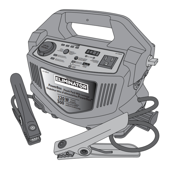
model no. 011-2002-8
IMPORTANT:
This manual contains important safety and
operating instructions. Read all instructions and
follow them with use of this product.
POWER PACK WITH
INVERTER
0 1 1 -2
0 0 2 -8
P o w e
r B o x
O n d u
l e u r -
P o w e
b l o c
r P a c
d ' a l i m
k W i t
e n t a t
h I n v
i o n
e r t e r
1 2 0 W
P o w e
r B o x
3 0 0
In v e r
t e r
O n d u
le u r
C r a n k
A s s is
a m p è
t A M P
r e s a u
S
d é m a
r r a g e
M D
INSTRUCTION
MANUAL
Advertisement
Table of Contents

Related Manuals for Eliminator 011-2002-8


Summary of Contents for Eliminator 011-2002-8
- Page 1 011-2002-8 POWER PACK WITH INVERTER 0 1 1 -2 0 0 2 -8 P o w e r B o x O n d u l e u r - P o w e b l o c r P a c d ’...
- Page 2 011-2002-8 | contact us 1-877-619-6321 DO NOT RETURN THIS PRODUCT TO THE STORE! QUESTIONS? CALL CUSTOMER SERVICE, HOTLINE: 1-877-619-6321...
- Page 3 TABLE OF CONTENTSTS Safety Information Key Parts List Important Information Operation Troubleshooting Technical Specification Warranty...
- Page 4 011-2002-8 | contact us 1-877-619-6321 • DO NOT use the power pack This manual contains information that relates to PROTECTING with life support systems or PERSONAL SAFETY and other medical equipment or PREVENTING EQUIPMENT devices. PROBLEMS. SHOCK AND FIRE HAZARD...
- Page 5 • DO NOT attempt to service or damage to the equipment and disassemble the power pack, a spark or explosion hazard. as it does not have user- It is recommended to store serviceable parts. the clamps in the appropriate holders. •...
- Page 6 011-2002-8 | contact us 1-877-619-6321 EXPLOSION AND FIRE • Always connect the clamps to HAZARD the correct terminals. A reverse polarity connection damages the • Never operate the power unit and / or creates a spark or pack near flammable items or explosion.
- Page 7 SAFETY PRECAUTIONS • DO NOT allow the positive and negative clamps of the WHEN WORKING WITH boosting cable to touch each BATTERIES other or another common metal Follow all instructions mentioned conductor. Doing so may cause by the manufacturer to avoid sparks and/ or damage the explosion of the battery.
- Page 8 011-2002-8 | contact us 1-877-619-6321 • Never smoke while handling the that can weld metals, thereby power pack or the batteries. causing severe burns on skin. • DO NOT operate the power pack • Wear complete eye and body...
- Page 9 • Recycling of the battery is appliance’s compatibility with recommended to prevent the modified sine wave (non- inappropriate disposal of the sinusoidal) AC waveform. battery. • Make sure the power pack is turned OFF when not in use, to SAFETY PRECAUTIONS prevent unnecessary battery FOR USING A discharge.
- Page 10 011-2002-8 | contact us 1-877-619-6321 FRONT PANEL AC/USB slide switch Reverse polarity LED indicator USB power indicator 12 V DC outlet AC outlet Correct connection indicator USB power port Battery capacity check button Positive cable clamp Battery capacity % indicators...
- Page 11 SIDE PANEL Boosting power switch...
- Page 12 011-2002-8 | contact us 1-877-619-6321 POWER PACK The MotoMaster Eliminator power ® pack is easy to use and designed COMPONENTS for years of reliable service, the AC/USB SLIDE SWITCH - The MotoMaster Eliminator power ® USB port provides power, when the...
- Page 13 CHARGING STATUS INDICATOR BATTERY CAPACITY CHECK BUTTON - This button - This LED indicator glows red, checks when the battery is charging and the remaining battery capacity glows in green when the battery is when pressed. fully charged. BATTERY CAPACITY % REVERSE POLARITY LED INDICATORS - This indicator INDICATOR - This LED indicator...
- Page 14 011-2002-8 | contact us 1-877-619-6321 TROUBLE LOADS • Metal halide arc (HMI) lights will be damaged. The electrical appliances mentioned HIGH SURGE LOADS below will be damaged when connected to this power pack. Some induction motors used in •...
- Page 15 AC APPLIANCE RUN TIME AC APPLIANCE WATTS* HOURS Cordless telephone (stand by) 20 h** Clock radio 10 h** Portable stereo 8 h** Fluorescent work light 4 h** Laptop computer Table lamp 1 h 20 min** 13” colour television 3/8" drill 10 min** * Actual power consumption as measured on sample products.
- Page 16 011-2002-8 | contact us 1-877-619-6321 PACKAGING CONTENTS MATERIAL NAME QUANTITY ILLUSTRATION 011-2002-8 12 V DC Bouton de SOCKET Battery vérification de la capacity OFF / ARRÊT check button capacité de la batterie AC/USB on indicator USB on indicator...
- Page 17 OPERATION OF AC APPLIANCES Check battery capacity status Slide the AC /USB switch (1) to to ensure the battery is fully the left and the indicator (2) will charged. Refer to Important glow (fig A). information Check the battery capacity by pushing the Digital Display Button to ensure the battery is fully charged.
- Page 18 011-2002-8 | contact us 1-877-619-6321 3. Plug the power cord (1) of the AC 4. Turn ON the AC appliance. appliance into the AC outlet (2) of 5. Recharge the power pack the power pack (fig B). immediately after use. Refer...
- Page 19 OPERATION OF 12 V DC APPLIANCES 3. Turn ON the DC appliance. Check the battery capacity % indicators to ensure the battery is 4. Recharge the power pack fully charged. Refer to Important immediately after use. Refer information page 13. to Recharging the power pack Plug the DC appliance’s power battery...
- Page 20 011-2002-8 | contact us 1-877-619-6321 OPERATION OF USB DEVICES Check the battery capacity % 3. Plug the other end of the USB indicators to ensure the battery is cable (1) into the device (2) fully charged. Refer to Important (fig E).
- Page 21 JUMP STARTING AN ENGINE 4. Slide the AC /USB switch (1) to the right and the USB power Make sure your vehicle is a indicator (2) will glow (fig F). negative ground system. If it is positive ground system vehicle or unsure, pleased consult the owners manual of your vehicle.
- Page 22 011-2002-8 | contact us 1-877-619-6321 RECHARGING THE POWER 4. Engage the transmission in park mode for an automatic PACK WITH THE AC CHARGER transmission vehicle or engage Turn OFF the boosting power the transmission in neutral for a switch (1) before attempting to manual transmission vehicle.
- Page 23 Connect the positive (red) Connect the negative (black) clamp (1) from the power pack to clamp (1) from the power pack the positive (+) terminal (2) of the to the chassis (2) of the vehicle battery in the vehicle (fig H). (fig I).
- Page 24 011-2002-8 | contact us 1-877-619-6321 9. Store the clamps in the 4. Disconnect the clamps from the battery of the vehicle if the appropriate holder on each side of connections are reversed and the power pack. repeat the steps 6 and 7, or 10.
- Page 25 RECHARGING THE POWER PACK Plug the 115 V AC charger (1) Turn OFF the AC/USB slide into charging input port (2) of switch (1) of the power pack the power pack (fig K). (fig J). 0 1 1 -2 0 0 2 -8 MM-112002-12 MM-112002-11 CAUTION! EQUIPMENT DAMAGE...
- Page 26 011-2002-8 | contact us 1-877-619-6321 The charging status indicator (1) glows red (fig M). 011-2 002-8 Po we On dul rBo x eur -blo Pow er c d’a Pac k lim ent Wit h 12 0 W atio n...
- Page 27 TROUBLESHOOTING PROBLEM POSSIBLE CAUSE SOLUTION The power pack cannot • The battery in the • Recharge the battery. jump start vehicle. power pack is not fully charged. • The engine start • Use a high capacity capacity exceeds the power pack. Make secure power pack jump- cable connections.
- Page 28 011-2002-8 | contact us 1-877-619-6321 PROBLEM POSSIBLE CAUSE SOLUTION The charging • No AC power at the AC • Ensure power is available at status LED indicator wall outlet. the AC wall outlet. does not glow. • The AC charger is faulty.
- Page 29 • Use a different TV, as the susceptibility to interference differs between various models. NOTE: ® For further assistance with the MotoMaster Eliminator Power Pack, contact customer WARNING! service at 1-877-619-6321. Do not disassemble the inverter, as it does not contain user- serviceable parts. WARNING! Have the inverter serviced by a qualified technician.
- Page 30 011-2002-8 | contact us 1-877-619-6321 ELECTRICAL SPECIFICATION Continuous output power 100 W Five minute AC output power 120 W AC output surge capacity (peak) 200 W Output voltage 104 - 125 V Output frequency 59 - 61 Hz...
- Page 31 This MotoMaster Eliminator product carries a one (1) year limited warranty ® against defects in workmanship and materials. At its discretion, MotoMaster Canada agrees to have any defective part(s) repaired or replaced free of charge, within the stated warranty period, when returned by the original purchaser with proof of purchase.
Need help?
Do you have a question about the 011-2002-8 and is the answer not in the manual?
Questions and answers
Should all LED lights be green when fully charged
No, the document states that the battery capacity is indicated by 4 LEDs but does not specify that all LEDs turn green when fully charged. The correct connection indicator glows green when properly connected, but other LEDs may have different colors for various statuses.
This answer is automatically generated
Im trying to find a replacement charger for my powerbox 011-2002-8 but I'm struggling to find either an OEM replacement or what is classified as an "approved charger" im hoping you can point me in the right direction. Thank you
The manual does not provide specific details on where to find a replacement charger for the Eliminator powerbox 011-2002-8. However, you can contact MotoMaster customer support at 1-877-619-6321 for assistance.
This answer is automatically generated