Advertisement
Advertisement

Related Manuals for Eliminator 011-1846-6


Summary of Contents for Eliminator 011-1846-6
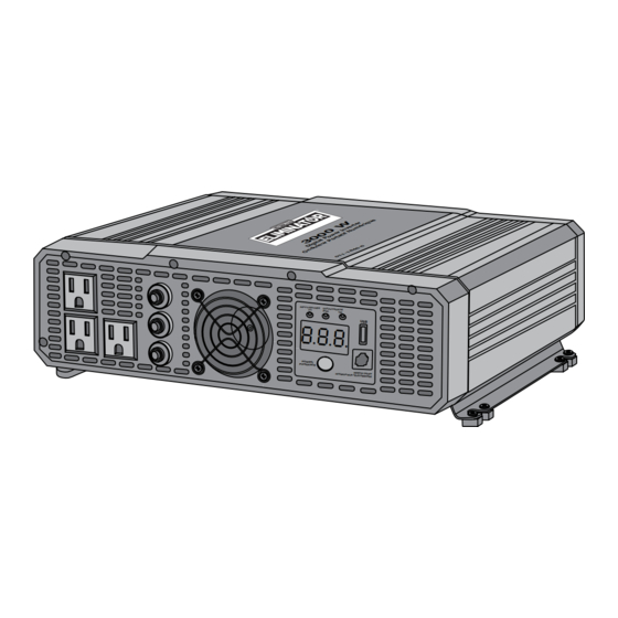
- Page 1 011-1846-6 3,000 WATT MODIFIED SINE WAVE DIGITAL INVERTER OUT PUT /SOR (KW ) POW ER/ PUIS SAN CE INSTRUCTION IMPORTANT: MANUAL This manual contains important safety and operating instructions. Read all instructions and follow them with use of this product.
-
Page 2: Table Of Contents
011-1846-6 | contact us 1-877-619-6321 TABLE OF CONTENTS Safety Information Key Parts List Important Information Assembly Instruction Operation Maintenance Troubleshooting Technical Specification Warranty DO NOT RETURN THIS PRODUCT TO THE STORE! QUESTIONS? CALL CUSTOMER SERVICE, HOTLINE: 1-877-619-6321... -
Page 3: Model No. 011-1846-6 | Contact Us 1-877
011-1846-6 | contact us 1-877-619-6321 FIRE HAZARD This manual contains information good condition. Operating the • Use care when operating that relates to protecting personal inverter with damaged wiring 110 V circuit. Incorrect • DO NOT cover or obstruct the safety and preventing equipment may void warranty. - Page 4 011-1846-6 | contact us 1-877-619-6321 SAFETY PRECAUTIONS batteries. These types of • Always wear complete eye and clothing protection. Avoid batteries emit explosive WHEN WORKING WITH • DO NOT use this inverter to hydrogen gas that can be...
- Page 5 011-1846-6 | contact us 1-877-619-6321 AC PANEL DC PANEL USB port AC Outlets Positive DC terminals Cooling fan and ventilation openings Remote switch port AC Outlet overload reset circuit Terminal covers Ground terminal Input indicator (V) Digital display...
- Page 6 011-1846-6 | contact us 1-877-619-6321 GENERAL USE recommended to keep inverter LOW BATTERY VOLTAGE DIGITAL DISPLAY - This always on, even when it is not The MotoMaster ® 3,000 Watt SHUTDOWN - This feature display shows input voltage in use.
- Page 7 011-1846-6 | contact us 1-877-619-6321 OUTPUT POWER INDICATOR VENTILATION OPENING - This • If the reading drops below 11 V • Use a high capacity battery, if (kW) - This indicator while the inverter is starting the the voltage still drops below...
- Page 8 011-1846-6 | contact us 1-877-619-6321 INPUT VOLTAGE LOAD PERFORMANCE CHART FOR THE 3,000 WATT MODIFIED SINE WAVE DIGITAL POWER INVERTER The table below depicts the input voltage limits under various operating 011-1846-6 conditions. This power inverter is modified sine wave inverter, it will perform good for most...
- Page 9 011-1846-6 | contact us 1-877-619-6321 LOAD RUN TIME SPECIFICATION APPLICATIONS PERFORMANCE RATING MODIFIED SINE WAVE PURE SINE WAVE LOAD RUN TIME PER BATTERY TYPE INVERTER INVERTER APPLIANCE WATT 22 NF (100 8 D (200) DUAL 6 V GOLF FOUR 8DS —...
- Page 10 011-1846-6 | contact us 1-877-619-6321 PACKAGING CONTENTS BEFORE INSTALLATION Follow all instructions including safety guidelines mentioned in this manual. MATERIAL NAME QUANTITY ILLUSTRATION DETERMINING BATTERY CAPACITY • Determine the battery capacity based on the type and requirement of load.
- Page 11 011-1846-6 | contact us 1-877-619-6321 MOUNTING THE INVERTER CHOOSING A LOCATION 1. Place the inverter in a suitable 3. Drill four mounting holes on the The inverter contains components that tend to produce arcs or sparks. It is not location and orientation.
-
Page 12: Assembly Instruction
011-1846-6 | contact us 1-877-619-6321 CONNECTING THE BATTERY CABLES 3. Remove the terminal covers (1), 4. With the positive (red) battery nuts (2), washers (3) and bolts (4) cable (1) passing through the 1. Make sure the inverter is turned... - Page 13 011-1846-6 | contact us 1-877-619-6321 9. Connect the ring connectors on the 10. Prepare a 14 AWG copper 5. With the negative (black) battery 7. Insert both terminal covers (1) cable (1) passing through the back onto the inverter (fig E).
- Page 14 011-1846-6 | contact us 1-877-619-6321 TURNING ON/OFF THE INVERTER RESTARTING THE INVERTER 11. Turn ON the inverter using power AFTER AC OUTPUT SHUTDOWN switch button. Refer operating 1. Press the power switch button (1) instructions page 27, step 1.
-
Page 15: Maintenance
011-1846-6 | contact us 1-877-619-6321 MAINTENANCE OPERATING SEVERAL LOADS The inverter will operate efficiently when maintained properly. 1. Press the power switch button 1. Make sure the USB device for half a second to turn ON the accepts 5 V and can be •... -
Page 16: Troubleshooting
011-1846-6 | contact us 1-877-619-6321 TROUBLESHOOTING PROBLEM POSSIBLE CAUSE SOLUTION PROBLEM POSSIBLE CAUSE SOLUTION The digital display • Low battery voltage • Recharge the battery. Check No output voltage • The inverter is in OFF • Turn ON the inverter. -
Page 17: Warranty
011-1846-6 | contact us 1-877-619-6321 ELECTRICAL SPECIFICATION This MotoMaster Eliminator product carries a two (2) year limited warranty ® against defects in workmanship and materials. At its discretion, MotoMaster Continuous AC output power 3000 W Canada agrees to have any defective part(s) repaired or replaced free of...
Need help?
Do you have a question about the 011-1846-6 and is the answer not in the manual?
Questions and answers
No longer have functioning remote switch . Is there a wiring diagram for the communications cable so I can make My Own remote turn on and monitoring system .