Advertisement
T3 Control Set Installation Guide
1. General
1.1 This T3 control set has been designed for
control of flow and water temperature in
an underfloor heating system. It is pre-
assembled and tested to ensure that it can
be fitted with the minimum of on-site labour
and commissioned immediately once fitted.
1.2 As supplied it is designed to connect to the
left hand side of an Emmeti manifold with
210mm between the centres of the flow
and return arms. It can also be used with
any other manifold built on this dimension.
The control set can also be altered to fit to
the right hand side of a manifold simply by
removing the bracket clips and turning the
control set elbows through 180 degrees
using the union fittings at the top and bottom
of the pump. The pump motor may need to
be rotated through 180 degrees to minimise
the space occupied by the control set and
allow access to the electrical connection box.
2. Connections & Dimensions
Fig.1 Overall Connections and Dimensions
Please note the overall dimensions of the control set and allow reasonable access at either side and the
front for installation and maintenance
1.3 There are other manifold sets to cater for
applications with different control needs or
higher flow rates for larger residential and
commercial applications:
•
U9700020 - Control set with thermostatic
valve (concealed dial) and pump, kvs 3.4
•
U9700060 - Control set with thermostatic
valve and variable speed class A pump, kvs 3.4
•
U9700030 - Control set with Thermostatic mixing
valve, thermal actuator and pump, kvs 3.4
•
U9700040* - Control set with motorised
mixing valve and pump, kvs 6.3
•
U9700050* - Control set with motorised
mixing valve and pump, kvs 8.0
* available with 3-point actuator, temperature
controller or weather compensator for mounting
on control set.
For a full description of each control set, please
consult our website www.emmeti.co.uk.
Fig. 2 Mounting Bracket Dimensions
T3 Control Set Installation Guide
3. Technical Data
Maximum static pressure
Maximum differential pressure
Maximum temperature
Operating temperature Range
Inlet connections
Outlet connections
Overall dimensions mm
Kvs
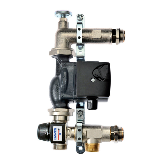
4. Control Set Contents
Pre-assembled control set including:
•
'L' pattern thermostatic mixing valve –
operating temperature range 35
C to 60
o
•
Grundfos UPS 25-60 circulating pump
•
Inlet tee assembly with 1"M swivel connector
to the underfloor return rail
•
Outlet elbow assembly with built-in
temperature gauge and 1"M swivel connector
to the underfloor flow rail
•
Mounting bracket with rubber supports
5. Installation
5.1 Remove the control set assembly carefully
from the packaging and check to ensure that
all components are in place and that there is no
damage to them.
5.2 The control set is supplied for connection to the
left hand side of the manifold but can be altered
very simply for connection to the right hand side.
(i) Remove the mounting bracket clips from the
control set by unscrewing the two screws
shown in Fig. 3 and rotating the upper and lower
elbows through 180
using the pump union nuts.
o
Fig. 3
Remove mounting
bracket clips
5.3 Re-fit the mounting bracket and rotate the
pump to an upright position as shown in Fig. 4.
10 bar
3 bar
95
o
C
Adjustable between 35
o
C and 60
2 x 1"M (G1)
2 x 1" M (G1) – swivel joint
311h x 189w x 132h
3.4
C
o
5.4 If the pump needs to be lowered into the
gap in the mounting bracket for space-saving
reasons, it will be necessary to remove the
Allen screws securing the pump motor and
rotate the motor so that the junction box is at
the front.
5.5 The control set can be attached to the
manifold either before or after the manifold
is secured to the wall. The control set should
be secured to a flat vertical surface able to
support the weight of the control set and
manifold. Using the dimensions shown in
Figs. 1 and 2, ensure that there is sufficient
space for installation and maintenance at the
intended position for the control set. The fixing
hole positions of the mounting bracket can be
marked through the mounting bracket itself.
5.6 A swivel joint is fitted to each side of the
control set for connecting to the 1" F manifold
tappings. The inlet tee swivel joint should be
connected to the return rail and the outlet
elbow swivel joint to the flow rail of the
manifold. Carefully offer up and screw the
swivel joint threads evenly into the manifold
using a 37mm A/F spanner: the use of a
31mm A/F spanner will also ensure that the
connection to the control set is kept tight – see
o
C
Fig. 4
Re-fit mounting
bracket
Advertisement
Table of Contents

Related Manuals for emmeti T3


Summary of Contents for emmeti T3
- Page 1 T3 Control Set Installation Guide T3 Control Set Installation Guide 1. General 3. Technical Data 1.1 This T3 control set has been designed for 1.3 There are other manifold sets to cater for Maximum static pressure 10 bar control of flow and water temperature in...
- Page 2 Emmeti literature for the 5.8 The primary flow and return pipework can now manifold. A pair of male blanking plugs, code be connected to the 2 x 1”M connections...
Need help?
Do you have a question about the T3 and is the answer not in the manual?
Questions and answers