Advertisement
sauder.com
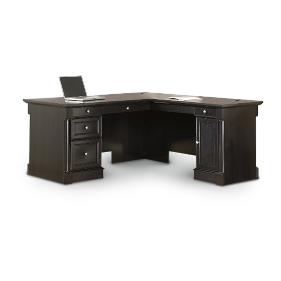
L-Shaped Desk
Avenue Eight Collection | Model 417714
Need help? Visit Sauder.com to view video assembly tips or chat with a live rep.
Prefer the phone? Call 1-800-523-3987.
Share your journey!
The original desktop.
NOTE: THIS INSTRUCTION
BOOKLET CONTAINS IMPORTANT
Safety INFORMATION.
PLEASE READ AND KEEP FOR
FUTURE REFERENCE.
English pg 1-48
Français pg 49-54
Español pg 55-60
Lot # 390961
04/28/16
Purchased: __________________
Be sure to give us a ring before
making any returns. 1-800-523-3987
Advertisement
Table of Contents

Related Manuals for Sauder 417714


Summary of Contents for Sauder 417714
- Page 1 Avenue Eight Collection | Model 417714 NOTE: THIS INSTRUCTION BOOKLET CONTAINS IMPORTANT SAFETY INFORMATION. Need help? Visit Sauder.com to view video assembly tips or chat with a live rep. PLEASE READ AND KEEP FOR FUTURE REFERENCE. Prefer the phone? Call 1-800-523-3987.
-
Page 2: Table Of Contents
SPACER (2) RIGHT MODESTY PANEL (1) KEYBOARD FRONT (1) MMM HALF DISK (8) LEFT MODESTY PANEL (1) KEYBOARD BACK (1) END MOLDING (4) RIGHT BACK (1) RIGHT KEYBOARD SIDE (1) LEFT BACK (1) LEFT KEYBOARD SIDE (1) Page 2 417714 www.sauder.com/services... -
Page 3: Part Identifi Cation
Now you know Part Identifi cation our ABCs. www.sauder.com/services 417714 Page 3... - Page 4 RIGHT DRAWER SIDE (Top Left) (1) D708 FILE DRAWER BOTTOM (1) TOP RIGHT DRAWER BACK (1) LEFT DRAWER SIDE (Top Left) (1) DRAWER BOX FRONT (1) RIGHT DRAWER SIDE (Top Right) (1) D716 DRAWER BOTTOM (2) D958 D716 D211 D708 D716 Page 4 417714 www.sauder.com/services...
-
Page 5: Hardware Identifi Cation
FELT DISC CARD - 1 LOCK - 1 LOCK COVER - 1 KNOB - 6 BRACKET - 1 RUBBER GROMMET - 3 GROMMET CAP - 3 CORD CLIP - 3 METAL PIN - 8 SLEEVE - 4 www.sauder.com/services 417714 Page 5... - Page 6 SILVER 1-1/4" MACHINE SCREW - 2 GOLD 1" MACHINE SCREW - 1 BLACK 7/8" MACHINE SCREW - 3 SILVER 3/4" PAN HEAD SCREW - 2 SILVER 9/16" LARGE HEAD SCREW - 2 SMALL BLACK 1-1/4" FLAT HEAD SCREW - 2 Page 6 417714 www.sauder.com/services...
- Page 7 BOTTOMS (I and J), RIGHT MODESTY PANEL (K), BACKS (N and O), LEGS (R and T), KEYBOARD UPRIGHT (VV), and both SPACERS (LLL). NOTE: Do not insert a SAUDER TWIST-LOCK® FASTENER into å the UPRIGHTS (E and F) at this time.
- Page 8 PANEL (QQ). Then, insert the metal end of a CAM DOWEL (2F) into each HIDDEN CAM. Do not tighten the HIDDEN CAMS in this step. Arrow Arrow Insert the metal end of the CAM DOWEL into the HIDDEN CAM. Page 8 417714 www.sauder.com/services...
- Page 9 Tap fi ve MOLDING CONNECTORS (17F) into the notches in å the MOLDINGS (BBB, CCC, DDD, EEE, FFF, GGG, and HHH). Use your hammer to tap the MOLDING CONNECTORS (17F) into the notches in the MOLDINGS. Flat end Flat end Flat end www.sauder.com/services 417714 Page 9...
- Page 10 NOTE: Do not overtighten the SCREWS into the TOP. å The large hole must be here. BLACK 1-1/4" FLAT HEAD SCREW (26 used in this step) Do not overtighten the SCREWS (7S). The large hole must be here. Page 10 417714 www.sauder.com/services...
- Page 11 UPRIGHT (F), Open end it will hang over the edge. GOLD 5/16" FLAT HEAD SCREW (12 used in this step) Open end Open end Open end These RAILS use the last holes from the open end. www.sauder.com/services 417714 Page 11...
- Page 12 NOTE: The EXTENSION SLIDES will be used later for the DRAWERS. å Push the black lever in and pull the SLIDE from the RAIL. GOLD 5/16" FLAT HEAD SCREW (4 used in this step) Open end Open end Page 12 417714 www.sauder.com/services...
-
Page 13: Right Keyboard
You have the choice of having your Keyboard Drawer on å the right or left side of your unit. Choose your assembly option and follow the remaining steps accordingly. KEYBOARD DRAWER ON RIGHT KEYBOARD DRAWER ON LEFT www.sauder.com/services 417714 Page 13... - Page 14 UPRIGHTS. Turn a SCREW into this hole. KEYBOARD DRAWER ON RIGHT Open end Open end Surface with TWIST-LOCK® FASTENERS Finished edge GOLD 5/16" FLAT HEAD SCREW (4 used in this step) Page 14 417714 www.sauder.com/services...
- Page 15 UPRIGHTS. Turn a SCREW into this hole. KEYBOARD Open end DRAWER ON LEFT Finished edge Surface without TWIST-LOCK® FASTENERS Open end GOLD 5/16" FLAT HEAD SCREW (4 used in this step) www.sauder.com/services 417714 Page 15...
- Page 16 Step 10 Fasten the HALF DISKS (MMM) to the PLINTHS (JJJ). Use å eight BROWN 1" FLAT HEAD SCREWS (12S). BROWN 1" FLAT HEAD SCREW (8 used in this step) The larger hole should be facing up. Page 16 417714 www.sauder.com/services...
- Page 17 Fasten four PLINTHS (JJJ) to the OUTER ENDS (A and C). å Use eight BLACK 9/16" LARGE HEAD SCREWS (1S). (28 used) BLACK 9/16" LARGE HEAD SCREW (36 used in this step) Use bottom holes Use bottom holes www.sauder.com/services 417714 Page 17...
- Page 18 HALF DISKS (MMM) on the PLINTHS (JJJ). BLACK 9/16" LARGE HEAD SCREW (20 used in this step) Use bottom holes Use bottom holes The END MOLDINGS (M35) should be centered over the HALF DISKS (MMM). Page 18 417714 www.sauder.com/services...
- Page 19 Tighten two TWIST-LOCK® FASTENERS. Surface with TWIST-LOCK® FASTENERS ® How to use the SAUDER TWIST-LOCK FASTENER 1. Insert the dowel end of the FASTENER into the hole of the adjoining part. NOTE: The dowel end of the FASTENER must remain fully inserted in the hole of the adjoining part while locking the FASTENER.
- Page 20 BLACK 1-7/8" FLAT HEAD SCREW (2 used in this step) w i t ® r f a - L O I S T r f a I S T w i t - L O ® Page 20 417714 www.sauder.com/services...
- Page 21 BLACK 1-7/8" FLAT HEAD SCREW (2 used in this step) Push the LEFT UPRIGHT (F) onto the TWIST-LOCK® FASTENERS (7F) å in the LEFT TOP (H2) and LEFT BACK (O). Tighten the TWIST-LOCK® FASTENERS. These edges should be even. www.sauder.com/services 417714 Page 21...
- Page 22 Push two CORD CLIPS (9P) into the holes in the LEFT TOP (H2). å NOTE: The CORD CLIPS are used to manage your cords. å BLACK 1-7/8" FLAT HEAD SCREW (2 used in this step) BLACK 9/16" LARGE HEAD SCREW (4 used for the CONNECTOR PLATE) Page 22 417714 www.sauder.com/services...
- Page 23 F A S I S T - L O C E R S T E N T E N ® E R S F A S BLACK 1-1/8" PAN HEAD SCREW (2 used in this step) www.sauder.com/services 417714 Page 23...
- Page 24 Fasten the LEFT SIDE SKIRT (SS) to å the LEFT BOTTOM (J). Use fi ve BLACK 9/16" LARGE HEAD SCREWS (1S). These edges should be even. BLACK 9/16" LARGE HEAD SCREW (14 used in this step) Page 24 417714 www.sauder.com/services...
- Page 25 Fasten the LEFT BACK SKIRTS (UU) to the å INNER LEFT END (D2), LEFT BOTTOM (J), (8 used) and LEFT SIDE SKIRT (SS). Use eight BLACK 9/16" LARGE HEAD SCREWS (1S). BLACK 9/16" LARGE HEAD SCREW (16 used in this step) www.sauder.com/services 417714 Page 25...
- Page 26 Fasten a SPACER (LLL) to the OUTER RIGHT END (A). å Tighten two TWIST-LOCK® FASTENERS. Surface with TWIST-LOCK® FASTENERS ® i t h f a c - L O S u r I S T Large hole should be located here. Page 26 417714 www.sauder.com/services...
- Page 27 BLACK 1-7/8" FLAT HEAD SCREW (2 used in this step) ® i t h f a c - L O S u r I S T r f a I S T w i t - L O ® www.sauder.com/services 417714 Page 27...
- Page 28 FASTENERS (7F) in the RIGHT TOP (G2) and RIGHT BACK (N). Tighten the TWIST-LOCK® FASTENERS. Large hole should be located here. i t h o f a c I O N S u r E N S E X T Page 28 417714 www.sauder.com/services...
- Page 29 Push a CORD CLIP (9P) into the hole in the RIGHT TOP (G2). å NOTE: The CORD CLIP is used to manage your cords. å BLACK 1-7/8" FLAT HEAD SCREW (2 used in this step) r f a I S T w i t - L O ® www.sauder.com/services 417714 Page 29...
- Page 30 Fasten the RIGHT SIDE SKIRT (RR) to the RIGHT BOTTOM (I). å Use four BLACK 9/16" LARGE HEAD SCREWS (1S). Surface with BLACK 9/16" LARGE HEAD SCREW TWIST-LOCK® (4 used for the CORNER BRACKETS) FASTENERS BLACK 1-7/8" FLAT HEAD SCREW (2 used in this step) Page 30 417714 www.sauder.com/services...
- Page 31 SKIRT (RR). Use eight BLACK 9/16" LARGE HEAD SCREWS (1S). Insert a GROMMET (10P) and GROMMET CAP (1P) into å the large hole in the RIGHT UPRIGHT (E). BLACK 9/16" LARGE HEAD SCREW (8 used in this step) www.sauder.com/services 417714 Page 31...
- Page 32 Tighten Risk of damage or Arrow injury. HIDDEN CAMS must be completely Arrow Maximum tightened. HIDDEN 210 degrees CAMS that are not completely tightened may loosen, and parts may separate. To Minimum completely tighten: 190 degrees Page 32 417714 www.sauder.com/services...
- Page 33 Tighten Risk of damage or Arrow injury. HIDDEN CAMS must be completely Arrow Maximum tightened. HIDDEN 210 degrees CAMS that are not completely tightened may loosen, and parts may separate. To Minimum completely tighten: 190 degrees www.sauder.com/services 417714 Page 33...
- Page 34 PANEL (K). Use two BLACK 1-1/8" PAN legs. And, you know, HEAD SCREWS (9S). your arms. BLACK 1-1/8" PAN HEAD SCREW (2 used in this step) BLACK 9/16" LARGE HEAD SCREW (4 used for the CONNECTOR PLATE) Page 34 417714 www.sauder.com/services...
- Page 35 Step Step 29 Fasten the HINGES (14H) to the DOOR (P). Use four å BLACK 1/2" FLAT HEAD SCREWS (11S). BLACK 1/2" FLAT HEAD SCREW (4 used in this step) www.sauder.com/services 417714 Page 35...
- Page 36 DOOR where it comes in contact with the RIGHT UPRIGHT (E). Mounting screw Fasten a KNOB (42K) to the DOOR (P). Use a GOLD 1" å MACHINE SCREW (50S). Hinge GOLD 1" MACHINE SCREW (1 used for the KNOB) Page 36 417714 www.sauder.com/services...
- Page 37 Adjusting screw (horizontal) To adjust the DOOR in or out (depth), loosen å the mounting screw one turn and move the DOOR in or out, as needed. Tighten the mounting screw after making adjustments. (vertical adjustment) www.sauder.com/services 417714 Page 37...
- Page 38 å KEYBOARD SHELF (AAA). Use four BROWN 1-1/2" FLAT HEAD SCREWS (14S). BROWN 1-1/2" FLAT HEAD SCREW Short fi nished edge (4 used in this step) These holes must be facing up. Short fi nished edge Page 38 417714 www.sauder.com/services...
- Page 39 Fasten the KEYBOARD HINGES (12H) to the å KEYBOARD SHELF (AAA). Use two SILVER 9/16" LARGE HEAD SCREWS (54S). SILVER 5/8" FLAT HEAD SCREW SILVER 9/16" LARGE HEAD SCREW (4 used in this step) (2 used in this step) www.sauder.com/services 417714 Page 39...
- Page 40 BLACK 7/8" MACHINE SCREW (1 used for the KNOB) GOLD 5/16" FLAT HEAD SCREW (2 used for the fi rst holes in the SLIDES) Page 40 417714 www.sauder.com/services...
- Page 41 Be sure the grooves in each part line up with each other on the inside of the drawer. Use top hole D716 Groove BLACK 1-9/16" FLAT HEAD SCREW (12 used in this step) D211 D708 D211 Groove www.sauder.com/services 417714 Page 41...
- Page 42 FRONT BRACKETS (6G). Use two BLACK 9/16" LARGE HEAD SCREWS (1S). Repeat this step for the right small drawer using DRAWER FRONT (GG). å BLACK 9/16" LARGE HEAD SCREW (4 used in this step) Push down Page 42 417714 www.sauder.com/services...
- Page 43 FRONTS (S and Z). Use eight BLACK 1-1/8" PAN HEAD SCREWS (9S). Tap down with your screwdriver and hammer. Push down D211 These edges should be even. These edges BLACK 1-1/8" PAN HEAD SCREW should be even. (8 used for the DRAWER FRONTS) www.sauder.com/services 417714 Page 43...
- Page 44 (4 used in this step) r r o Open end l i d s i o t e n SILVER 1-1/4" MACHINE SCREW r r o (1 used for the KNOB) Page 44 417714 www.sauder.com/services...
- Page 45 D211 Open end l i d s i o t e n SILVER 1-1/4" MACHINE SCREW (1 used for the KNOB) GOLD 5/16" FLAT HEAD SCREW (4 used in this step) www.sauder.com/services 417714 Page 45...
- Page 46 FILE DRAWER LEFT SIDE (D32). Fasten the LOCK BRACKET (5J) to the FILE DRAWER å RIGHT SIDE (D211). Use a BROWN 7/16" LARGE HEAD SCREW (6S). D211 BROWN 7/16" LARGE HEAD SCREW (1 used in this step) Page 46 417714 www.sauder.com/services...
- Page 47 SILVER 3/4" PAN HEAD SCREWS (52S). DRAWER ON LEFT Push the LOCK COVER (10J) over the LOCK (1J). å Almost time to celebrate! With a nap. SILVER 3/4" PAN HEAD SCREW (2 used in this step) www.sauder.com/services 417714 Page 47...
-
Page 48: Safety
This completes assembly. Clean with your favorite furniture polish or a damp cloth. Wipe dry. å And to celebrate, why not share your success story? KEYBOARD DRAWER ON LEFT 70 lbs. 50 lbs. 20 lbs. 5 lbs. 5 lbs. 20 lbs. 40 lbs. 25 lbs. 35 lbs. (4 used) Page 48 417714 www.sauder.com/services... -
Page 49: Français
Modèle 417714 Bureau en L Utilisez les instructions d’ a ssemblage en français avec les schémas NOUS SOMMES LA POUR VOUS AIDER! étape par étape du manuel d’instruction en anglais. Chaque étape en Nous faisons de notre mieux pour nous assurer que votre meuble arrive français correspond à... - Page 50 Pour commencer l'assemblage, enfoncer une FIXATION TWIST-LOCK® GAUCHE INTERNE (D2) et au MONTANT GAUCHE (F). Utiliser quatre VIS SAUDER (7F) dans les gros trous des EXTRÉMITÉS EXTERNES (A et C). DORÉES TÊTE PLATE 8 mm (3S). Répéter cette étape pour les EXTRÉMITÉS INTERNES (B2 et D2), les REMARQUE : Pour chaque GLISSIÈRE D'EXTENSION, faire tourner une VIS dans...
- Page 51 Faire tourner deux CLIPS POUR CORDON (9P) dans les trous du DESSUS GAUCHE (H2). Utilisation de la FIXATION TWIST-LOCK® SAUDER REMARQUE : Les CLIPS POUR CORDONS servent à gérer les cordons. 1. Insérer l'extrémité fi letée de la FIXATION dans le trou de la pièce attenante.
- Page 52 Fixer le DESSOUS DROIT (I) au MONTANT DROIT (E). Utiliser deux VIS NOIRES TÊTE PLATE 48 mm (2S). Fixer la PLINTHE LATÉRALE DROITE (RR) au DESSOUS DROIT (I). Utiliser quatre VIS NOIRES TÊTE LARGE 14 mm (1S). Page 52 417714 www.sauder.com/services...
- Page 53 DEVANT DE TIROIR (9G et 10G). Utiliser huit VIS NOIRES TÊTE LARGE 14 mm (1S). Fixer les DEVANTS DE TIROIR (U et BB) sur les DEVANTS DE CAISSON DE TIROIR (S et Z). Utiliser huit VIS NOIRES TÊTE GOUTTE DE SUIF 28 mm (9S). www.sauder.com/services 417714 Page 53...
- Page 54 GUIDES POUR DOSSIERS (8B) et appuyer cette ARMATURE POUR DOSSIERS sur le CÔTÉ GAUCHE DE TIROIR DE CLASSEUR (D32). Fixer la CONSOLE DE SERRURE (5J) au CÔTÉ DROIT DE TIROIR DE CLASSEUR (D211). Utiliser une VIS MARRON TÊTE LARGE 11 mm (6S). Page 54 417714 www.sauder.com/services...
-
Page 55: Español
Modelo 417714 Escritorio en L Use estas instrucciones de ensamblaje en español junto con las fi guras paso-a- ESTAMOS AQUI PARA AYUDAR! paso provistas en el folleto inglés. Cada paso en español corresponde al mismo Tratamos de asegurar que su mueble llega en condición excelente. Nuestros represen- tantes de Servicio al Cliente son amables y listos para ayudarle con servicio rápido y... - Page 56 PARAL DE ESTANTE DE TECLADO (VV) y dos ESPACIADORES (LLL). agujeros que se alinean con los agujeros del EXTREMO y PARAL. Atornille un NOTA: No inserte un SUJETADOR TWIST-LOCK® SAUDER en los TORNILLO dentro de este agujero. PARALES (E y F) en este momento.
- Page 57 GRANDE de 14 mm (1S). Introduzca girando dos GRAPAS DE CABLE (9P) dentro los agujeros en Cómo utilizar el SUJETADOR TWIST-LOCK® SAUDER el PANEL SUPERIOR IZQUIERDO (H2). 1. Inserte el extremo con cabilla del SUJETADOR dentro del agujero de la NOTA: Las GRAPAS DE CABLE se utilizan para dirigir sus cables.
- Page 58 Fije el FONDO DERECHO (I) al PARAL DERECHO (E). Utilice dos TORNILLOS NEGROS DE CABEZA PERDIDA de 48 mm (2S). Fije el FALDÓN LATERAL DERECHO (RR) al FONDO DERECHO (I). Utilice cuatro TORNILLOS NEGROS DE CABEZA GRANDE de 14 mm (1S). Page 58 417714 www.sauder.com/services...
- Page 59 CAJÓN (9G y 10G). Utilice ocho TORNILLOS NEGROS DE CABEZA GRANDE de 14 mm (1S). Fije las CARAS DE CAJÓN (U y BB) a los FRENTES DE CAJÓN (S y Z). Utilice ocho TORNILLOS NEGROS DE CABEZA REDONDA de 28 mm (9S). www.sauder.com/services 417714 Page 59...
- Page 60 VARILLAS DE ARCHIVERO (8B) y presione este CORRIMIENTO DE ARCHIVERO sobre el LADO IZQUIERDO DE CAJÓN DEL ARCHIVERO (D32). Fije el SOPORTE DE CERRADURA (5J) al LADO DERECHO DE CAJÓN DEL ARCHIVERO (D211). Utilice un TORNILLO MARRÓN DE CABEZA GRANDE de 11 mm (6S). Page 60 417714 www.sauder.com/services...
- Page 61 à Les téléviseurs peuvent être particulièrement un téléviseur. cet eff et. lourds. De plus, le poids et l’emplacement du tube image ont tendance à rendre les téléviseurs instables et enclins à tomber vers l’ a vant. www.sauder.com/services 417714 Page 61...
- Page 62 Además, el peso y la ubicación del tubo de imagen tienden a causar la inestabilidad de televisores y propensa a volcarse hacia adelante. Page 62 417714 www.sauder.com/services...
- Page 63 GARANTIE LIMITÉE DE 5 ANS 1. Sauder Woodworking Co. (Sauder®) off re une couverture de garantie limitée à l’ a cheteur 4. La présente garantie ne s’ a pplique qu’ a ux défauts garantis qui se produisent pour initial du présent produit pendant une période de cinq ans à...
- Page 64 Dear Valued Customer: So, how did it go? Thanks so much for choosing Sauder® furniture. I hope the Set a world record for speed? purchase and assembly process was a positive experience Feeling good about yourself? and you feel good about the furniture you just built. If you Nice.
Need help?
Do you have a question about the 417714 and is the answer not in the manual?
Questions and answers