Advertisement
1440 Ferris Place · Bronx · New York· 10461-3699
Model Number:
3234 - Fail Secure
3234RS - Fail Safe
Model Number:
3234W - Fail Secure
3234WRS - Fail Safe
STANDARD FEATURES
Face Plate - 3234, 2-3/4" x 1-1/8"
3234W, 3-3/4" x 1-1/4"
3478, 4-7/8" x 1-1/4"
Mortise Type - 1" backset (Smallest in the Industry)
Durability - 500,000 Life Cycles
Holding Force - 1,200 Pounds (Static Force)
- 70 ft-lb (Dynamic Force)
All stainless steel locking parts
Solid Cast Latch - Stainless Steel
Cavity: Width 5/8", Height 1-1/8", Depth 1/2"
Non-handed
Heavy-duty latch spring
Silent Operation
Intermittent Duty with the Standard versions
Intermittent and Continuous Duty with the LC versions
Micro Solenoid assembly
Fail-Secure:(standard action) unlocks with power
Fail-Safe: RS (reverse action) unlocks when power is off
US3 (Polished Brass)
US4 (Satin Brass)
US10B (Dark Bronze)
US26 (Bright Chrome)
US26D (Satin Chrome)
US32D (Satin Stainless Steel)
Model Number:
3478 - Fail Secure
3478RS - Fail Safe
FINISHES
3234
3234W
3478
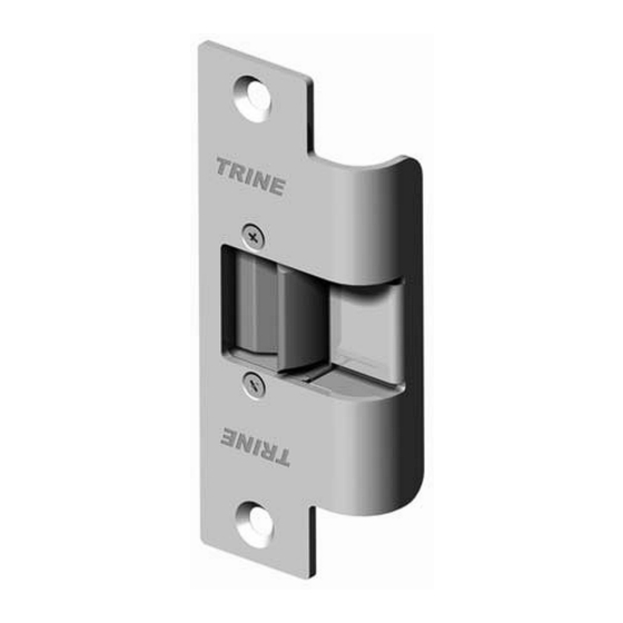
TRINE 3000 SERIES ELECTRIC RELEASES
Congratulations on the purchase of this quality TRINE
security product.
This product has been designed to install easily, perform
reliably, and provide years of trouble free security.
In order for this product to fulfill its objectives, certain
steps must be performed by the installer, and certain site
conditions must be satisfied.
Before proceeding with your installation, please review
the following list of items. If you have any questions first
please finish reading this document to see if the
information you require is contained in this document,
otherwise please call:
TRINE TECH SUPPORT (718) 829-2332 EXT. 425,
or visit the TRINE Website www.TrineOnline.com.
The TRINE Model #3234, #3234W & Model #3478 are
designed for new installation or retrofitting into metal,
wood and aluminum door frames. Be sure that you have
ordered the correct TRINE strike for your application.
RECOMMENDED INSTALLATION SEQUENCE:
1. Verify strike is proper for the door into which it is to be
installed.
2. Verify that you have all parts required to complete the
installation.
3. Verify that the new electric release operates with the
existing power supply/control circuit (retrofit
applications); or verify that the new power supply/
control circuit operates the new electric release (new
installations).
4. Locate and clearly mark the circuit breaker which
provides ac power to your transformer/ power supply
or that supplies power to the receptacle into which you
will plug your transformer/power supply. This will
enable you to safely cut power during installation, and
permit troubleshooting if required.
5. Verify that the receptacle or circuit providing power to
the electric release is not controlled by a wall switch,
time clock, or other external device.
6. Verify that the circuit/receptacle used for the locking
system is not powering any other equipment.
Remember that interruption of power to your locking
system could prevent access into the protected area,
or jeopardize the security/safety of the site's
occupants.
7. Verify that the door and associated components are in
good working order.
8. Install electric release as per attached guidelines.
9. Wire electric release as per attached guidelines.
10. Perform final test of completed installation.
Advertisement
Table of Contents

Related Manuals for Trine 3000 Series

Summary of Contents for Trine 3000 Series
- Page 1 TRINE TECH SUPPORT (718) 829-2332 EXT. 425, or visit the TRINE Website www.TrineOnline.com. Model Number: 3234 - Fail Secure The TRINE Model #3234, #3234W & Model #3478 are 3234RS - Fail Safe designed for new installation or retrofitting into metal, Model Number: wood and aluminum door frames.
-
Page 2: Getting Started
RIGHT HAND OUTSIDE (LH) (RH) powered for extended periods, commonly referred to as CONTINUOUS DUTY. The TRINE LC version of MODEL # 3234, 3234W, #3478, # OUTSIDE LEFT HAND RIGHT HAND 3234-RS, #3234W-RS and #3478-RS can be used for REVERSE BEVEL... -
Page 3: Power Sources
TRINE strike you then add a sounding device as shown in the accompanying have, that the circuitry supplying the voltage is operating wiring diagrams. -
Page 4: Installation Drawings
INSTALLATION DRAWINGS METAL AND WOOD FRAME INSTALLATION The 3478's 4-7/8" x 1-1/4" faceplate requires the least amount of jamb preparation when compared with other electric OPTIONAL 1 1/4" strikes. 1/16" THICK 1 1/4" SHIM 1 1/4" 1 1/4" 3/32" 3/4" 1 1/4"... -
Page 5: Wiring Diagram
INSTALLATION DRAWINGS (Continued) METAL FRAME INSTALLATION The 3234's 2-3/4" x 1-1/4" faceplate requires the least amount of jamb preparation when compared with other electric strikes. 1 1/8" 1 11/16" 1/8" OPTIONAL 5/8" 1 1/8" 1/16" THICK SHIM 1 1/32" 5/8" 5/8"... - Page 6 WIRING DIAGRAM (continued) FIGURE 3 USING AC TRANSFORMER 24V AC OR 12V AC TRANSFORMER PUSH RECTIFIER* BUTTON FAIL-SECURE NORMALLY OPEN ELECTRIC LC100** STRIKE TO 120V AC LINE BLACK * The rectifier can be positioned before of after the push button in the circuit.
Need help?
Do you have a question about the 3000 Series and is the answer not in the manual?
Questions and answers