Allen-Bradley SLC ControlNet 1747-SCNR Installation Instructions Manual
Scanner module
Hide thumbs
Also See for SLC ControlNet 1747-SCNR:
- Reference manual (144 pages) ,
- Installation instructions manual (20 pages)
Table of Contents
Advertisement
Quick Links
Download this manual
See also:
Reference Manual
SLC ControlNet Scanner Module
Catalog Number 1747-SCNR
Use this document to help you install the ControlNet™ 1747-SCNR
Scanner module.
For information about
preventing electrostatic discharge
compliance to European Union Directives
related publications
module features
preparing the module for installation
selecting the ControlNet node address
inserting the 1747-SCNR scanner into the chassis
connecting to a ControlNet network
cables
applying chassis power
status indicators
specifications
Installation Instructions
See page
2
2
3
4
5
6
6
8
10
11
15
17
Publication 1747-5.36 - May 2000
Advertisement
Table of Contents

Subscribe to Our Youtube Channel
Related Manuals for Allen-Bradley SLC ControlNet 1747-SCNR


Summary of Contents for Allen-Bradley SLC ControlNet 1747-SCNR
- Page 1 Installation Instructions SLC ControlNet Scanner Module Catalog Number 1747-SCNR Use this document to help you install the ControlNet™ 1747-SCNR Scanner module. For information about See page preventing electrostatic discharge compliance to European Union Directives related publications module features preparing the module for installation selecting the ControlNet node address inserting the 1747-SCNR scanner into the chassis connecting to a ControlNet network...
-
Page 2: Prevent Electrostatic Discharge
SLC ControlNet Scanner Module Prevent Electrostatic Discharge The scanner module is sensitive to electrostatic discharge. Electrostatic discharge can damage integrated circuits or ATTENTION semiconductors if you touch backplane connector pins. Follow these guidelines when you handle the module: • touch a grounded object to discharge static potential •... -
Page 3: Related Publications
Voltage by applying the safety requirements of EN 61131-2 Equipment Requirements and Tests. For specific information required by EN 61131-2, see the appropriate sections in this publication as well as the following Allen-Bradley publications: • Industrial Automation Wiring and Grounding Guidelines For Noise Immunity, publication 1770-4.1... -
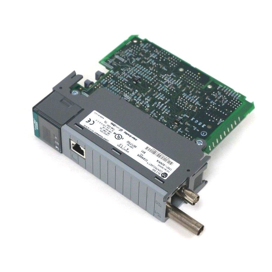
Page 4: Identify Scanner Module Features
SLC ControlNet Scanner Module Identify Scanner Module Features Use this illustration to identify the features of the 1747-SCNR Scanner module. Node Address and Status Display Displays scanner node address and status Channel B Status Indicator Channel A Module Status Indicator Status Indicator Indicates whether the device is powered and is functioning properly... -
Page 5: Prepare For Module Installation
(RSLogix 500 41523 Before you install the module, you must know how to: • program and operate an Allen-Bradley SLC 500 programmable controller • install and configure the devices on your ControlNet network Make Sure That Your Processor and Scanner Are Compatible... - Page 6 SLC ControlNet Scanner Module Select the ControlNet Node Address Select the ControlNet node address of the 1747-SCNR by setting the two 10-digit rotary switches on the top of the scanner. Valid switch settings range from 01 through 99. Zero (00) is not a valid node address.
- Page 7 SLC ControlNet Scanner Module 2. Select a slot for the module in the chassis. Choose any slot except the left-most slot of the first chassis, which is reserved for either the SLC 500 processor. 3. Insert the module into the slot you have selected. We recommend that you insert the 1747-SCNR Scanner as close to the chassis power supply as possible.
- Page 8 Connect to a ControlNet Network Connect the 1747-SCNR Scanner module to a ControlNet network via a tap with a 1 m (39.4 in.) drop cable. Four Allen-Bradley ControlNet taps are available from Rockwell Automation as shown below. Right-angle Y-tap Right-angle T-tap...
- Page 9 SLC ControlNet Scanner Module Remove the tap’s dust cap—located on the straight or right-angle connector—and set it aside. If your network supports Connect the tap’s straight or right-angle connector nonredundant media to the channel A connector on the scanner—channel B is not used.
- Page 10 Isolated-bulkhead (jack to jack) 1786-BNCJI Terminators (BNC-75Ω) 1786-XT 1. For a complete list of Allen-Bradley ControlNet cable system components that are available from Rockwell Automation and cable system components available from other suppliers, see the ControlNet Cable System Component List, publication AG-2.2. Important:...
-
Page 11: Alphanumeric Display
SLC ControlNet Scanner Module Apply Chassis Power Node Address and Status Display 30750-M When you apply chassis power, the module address and status display cycles through the following displays: 1. POST - The 1747-SCNR runs Power On Self Test. 2. 1111, 2222, etc. - The 1747-SCNR is executing its startup sequence. - Page 12 SLC ControlNet Scanner Module OK Indicator and Display Mnemonics The OK indicator is handled consistently with the ControlNet specifications for the Identity object. Sequence OK Alpanumeric Module Status Description Probable Recommended Indicator Display Word (M1 file) Cause Action Startup Alternately POST Power was No action...
- Page 13 SLC ControlNet Scanner Module Sequence OK Alpanumeric Module Status Description Probable Recommended Indicator Display Word (M1 file) Cause Action Run time Green The scanner is The SLC If you want to in run mode. processor or put the scanner adapter in into program slot 0 is in run mode, either...
- Page 14 SLC ControlNet Scanner Module Sequence OK Alpanumeric Module Status Description Probable Recommended Indicator Display Word (M1 file) Cause Action Run time Flashing 0x23 Connections Remote Check to see if Green Configured but devices are the remote only not on line. devices are 25% are correctly...
-
Page 15: Status Indicators
SLC ControlNet Scanner Module Sequence OK Alpanumeric Module Status Description Probable Recommended Indicator Display Word (M1 file) Cause Action Errors Flashing DUPL 0x44 Duplicate Another Power down A#XX node. device with the 1747-SCNR the same module and ControlNet change the address is on network the link. - Page 16 SLC ControlNet Scanner Module Indicator Probable Cause Recommended Action Color Channel disabled Program network for redundant media, if required. Steady Normal operation No action required. Green • Check media for broken cables, Flashing Temporary network Green/Off errors loose connectors, missing terminators, etc.
-
Page 17: Specifications
SLC ControlNet Scanner Module Specifications Module Location Slot 1 or above Module Defaults Node Address -00 Maximum Backplane Current 900 mA @ 5V dc Isolated Voltage Optical Isolation between backplane and ControlNet channel 1 Megohm resistor from ControlNet channel to chassis Environmental Conditions: Operational Temperature... - Page 18 SLC ControlNet Scanner Module CSA Hazardous Location Approval CSA certifies products for general use as well as for use in hazardous locations. Actual CSA certification is indicated by the product label as shown below, and not by statements in any user documentation. Example of the CSA certification product label: CL I, DIV 2 GP A,B,C,D...
- Page 19 •Avant de débrancher les connecteurs, couper le courant ou s’assurer que l’emplacement est reconnu non dangereux. Attacher tous connecteurs fournis par l’utilisateur et reliés aux circuits externes d’un appareil Allen-Bradley à l ‘aide de vis, loquets coulissants, connecteurs filetés ou autres moyens permettant aux connexions de résister à...
- Page 20 Allen-Bradley is a registered trademark of Rockwell Automation. SLC is a trademark of Rockwell Automation. ControlNet is a trademark of ControlNet International. Microsoft Windows is a registered trademark of Microsoft Corporation. RSNetWorx for ControlNet and RSLogix 500 are trademarks of Rockwell Software, Inc.
Need help?
Do you have a question about the SLC ControlNet 1747-SCNR and is the answer not in the manual?
Questions and answers