
Related Manuals for Allen-Bradley FLEX I/O 1794-IJ2


Summary of Contents for Allen-Bradley FLEX I/O 1794-IJ2
- Page 1 Allen-Bradley User FLEX I/O Frequency Manual Input Module (Cat. No. 1794-IJ2) Allen-Bradley Replacements...
- Page 2 DeviceNet, DeviceNetManager, and RediSTATION are trademarks of Allen-Bradley Company, Inc. PLC, PLC-2, PLC-3, and PLC-5 are registered trademarks of Allen-Bradley Company, Inc. Windows is a trademark of Microsoft. Microsoft is a registered trademark of Microsoft IBM is a registered trademark of International Business Machines, Incorporated.
- Page 3 Allen-Bradley programmable controllers. The manual helps you install, program and troubleshoot your module. Audience You must be able to program and operate an Allen-Bradley programmable controller to make efficient use of your FLEX I/O module. In particular, you must know how to program block transfers.
- Page 4 Using This Manual Conventions We use these conventions in this manual: In this manual, we show: Like this: that there is more information about a topic in another chapter in this manual that there is more information about the topic in another manual For Additional Information For additional information on FLEX I/O systems and modules, refer to the following documents:...
- Page 5 1794-5.12 1794-NM1 Mounting Kit 1794-2.13 1794-PS1 24V dc Power Supply 1794-5.35 Summary This preface gave you information on how to use this manual efficiently. The next chapter introduces you to the frequency module. Allen-Bradley Replacements Publication 1794-6.5.11 - November 1997...
- Page 6 Using This Manual Publication 1794-6.5.11 - November 1997...
-
Page 7: Table Of Contents
Chapter Summary ........2-13 Allen-Bradley Replacements... - Page 8 toc–ii Table of Contents – FLEX I/O Frequency Input Module Programming Your Frequency Chapter 3 What This Chapter Contains ....... . . 3-1 Input Module Enter Block Transfer Instructions .
- Page 9 Digital Outputs......... .B-2 DC to DC Converters (24V dc power supplies) ....B-3 Allen-Bradley Replacements Publication 1794-6.5.11 - November 1997...
-
Page 10: What This Chapter Contains
Chapter Overview of the Frequency Input Module What This Chapter Read this chapter to familiarize yourself with the 1794-IJ2 module. Contains For information on See page How You Use the Module ......What the Frequency Input Module Does . -
Page 11: What The Frequency Input Module Does
These instructions let the adapter read input values and status from the module, and let you write output values and configure the module’s mode of operation. The following illustration describes the communication process. Allen-Bradley Replacements Publication 1794-6.5.11 - November 1997... -
Page 12: Typical Applications
Overview of the Frequency Input Module The adapter transfers your configuration data External devices transmit to the module using a BTW. frequency signals to the module. Flexbus Allen-Bradley Allen-Bradley 1794-IJ2 FREQUENCY INPUT 2 CHANNEL 24VDC ADAPTER LOCAL POWER SUPPLY FAULT... -
Page 13: Input Capabilities
• monitor the acceleration (rate of speed change) √ • operate acceleration alarm (rate of change) • scale the frequency √ • monitor the direction of shaft rotation √ • wire-off alarm with dc devices √ • missing pulse alarm Allen-Bradley Replacements Publication 1794-6.5.11 - November 1997... -
Page 14: Output Capabilities
Overview of the Frequency Input Module Output Capabilities The 1794-IJ2 module has 2 assignable outputs. These outputs are designed for applications that require fast response. The outputs: • are current sourcing at 10-31.2V dc (1A maximum per output) • are electrically fused/current limited to 3A •... -
Page 15: Termination On Number Of Pulses
2 seconds to report a missing pulse. Another user parameter, Number of Pulses to Terminate Sampling, is provided for those situations where many pulses are expected within the sampling window, such that early determination of frequency is possible. Allen-Bradley Replacements Publication 1794-6.5.11 - November 1997... -
Page 16: Missing Pulse Multiplier
Overview of the Frequency Input Module During normal operation, there is a sufficient number of pulses to prevent the module from entering the 2 second extension mode. Once the user defined number of pulses is reached within the sampling window, the frequency is immediately reported. -
Page 17: Direction Detection
Direction Detection - Principle of Operation Clockwise Rotation 2 x M Sensor 0 Sensor 1 Gate Input Frequency Input IJ2 Module Sensor 0 (F) Clockwise Rotation Sensor 1 (G) Counter Sensor 0 (F) Clockwise Sensor 1 (G) Rotation Allen-Bradley Replacements Publication 1794-6.5.11 - November 1997... -
Page 18: Chapter Summary
Overview of the Frequency Input Module Chapter Summary In this chapter, you learned about the frequency input module, block transfer communication, and details of how the module functions. Now you can install the module. Install the IJ2 Module Publication 1794-6.5.11 - November 1997... - Page 19 1-10 Overview of the Frequency Input Module Allen-Bradley Replacements Publication 1794-6.5.11 - November 1997...
-
Page 20: What This Chapter Contains
Chapter How to Install Your Frequency Input Module What This Chapter In this chapter, we tell you about: Contains For information on See page Before You Install Your Module ......2-1 European Union Directives . -
Page 21: Low Voltage Directive
EN 61131-2 Programmable Controllers, Part 2 – Equipment Requirements and Tests. For specific information required by EN 61131-2, see the appropriate sections in this publication, as well as the following Allen-Bradley publications: • Industrial Automation Wiring and Grounding Guidelines For Noise Immunity, publication 1770-4.1... -
Page 22: Wiring The Terminal Base Units (1794-Tb3G Shown)
How to Install Your Frequency Input Module Methods of wiring the terminal base units are shown in the illustration below. Wiring the Terminal Base Units (1794-TB3G shown) ATTENTION: Do not daisy chain power or ground from the terminal base unit to any ac or dc digital module terminal base unit. -
Page 23: Installing The Module
Proceed as follows: Position terminal base at a slight angle and hooked over the top of the DIN rail. Allen-Bradley Replacements Publication 1794-6.5.11 - November 1997... - Page 24 How to Install Your Frequency Input Module Slide the terminal base unit over tight against the adapter. Make sure the hook on the terminal base slides under the edge of the adapter and the flexbus connector is fully retracted. Press down on the terminal base unit to lock the terminal base on the DIN rail.
-
Page 25: Panel/Wall Mounting
(not included) Terminal Base Unit (not included) To install the mounting plate on a wall or panel: 1. Lay out the required points on the wall/panel as shown in the drilling dimension drawing. Allen-Bradley Replacements Publication 1794-6.5.11 - November 1997... -
Page 26: Mounting The Frequency Input Module On The Terminal Base Unit
How to Install Your Frequency Input Module Drilling Dimensions for Panel/Wall Mounting of FLEX I/O (58.5) (35.5) (58.5) (35.5) (35.5) Inches (Millimeters) .83 (21) 2. Drill the necessary holes for the #6 self-tapping mounting screws. 3. Mount the mounting plate (1) for the adapter module using two #6 self-tapping screws (18 included for mounting up to 8 modules and the adapter). - Page 27 5. Press firmly and evenly to seat the module in the terminal base unit. The module is seated when the latching mechanism (7) is locked into the module. 6. Repeat the above steps to install the next module in its terminal base unit. Allen-Bradley Replacements Publication 1794-6.5.11 - November 1997...
-
Page 28: Connecting Wiring For Your Frequency Input Module
How to Install Your Frequency Input Module Connecting Wiring for Your Wiring to the module is made through the terminal base unit on which the Frequency Input Module module mounts. Compatible terminal base units are: Module 1794-TB3G 1794-TB3GS 1794-IJ2 1794-TB3G 1794-TB3GS 9 10 11 12 13 14 15 18 19 20 21 22 23... -
Page 29: Connecting Wiring Using A 1794-Tb3G And -Tb3Gs
If power is not applied, the module position will appear to the adapter as an empty slot in your chassis. If the adapter does not recognize your module after installation is completed, cycle power to the adapter. Allen-Bradley Replacements Publication 1794-6.5.11 - November 1997... -
Page 30: Wiring Connections For The 1794-Ij2 Frequency Input Module
How to Install Your Frequency Input Module 2-11 Wiring connections for the 1794-IJ2 Frequency Input Module Channel 0 Terminals Channel 1 Terminals Types of Inputs Power Input Power Input Frequency 1, 2 24V dc IEC1+ Proximity 24V dc Contact Switch 500mV ac Magnetic Pickup 50mV ac Magnetic Pickup 6V ac Vortex... -
Page 31: Examples Of Wiring To A 1794-Tb3G Terminal Base Unit
16 17 18 19 20 21 22 23 24 25 26 27 28 29 30 31 32 33 34 35 36 37 38 39 40 41 42 43 44 45 46 47 48 49 50 51 Power External Power Supply #1 10-31.2V dc @ 1A LOAD 0 Allen-Bradley Replacements Publication 1794-6.5.11 - November 1997... -
Page 32: Module Indicators
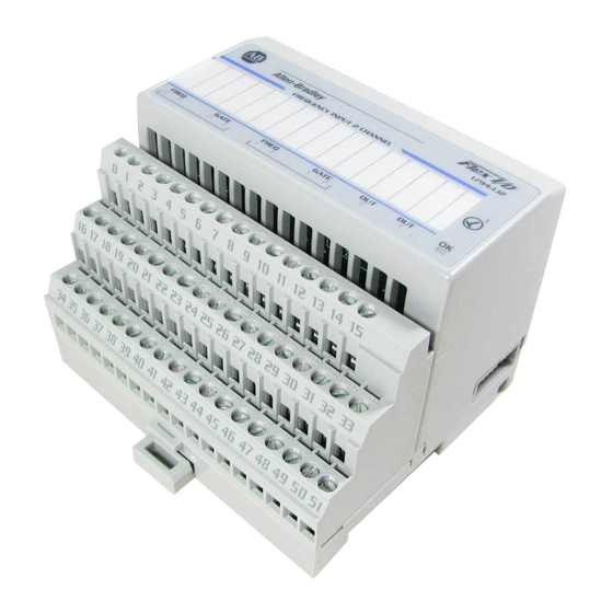
(F) for each input, and an input status indicator for each input (0 or 1) and an output indicator for each output (0 or 1). Allen-Bradley 1794-IJ2 FREQUENCY INPUT 2 CHANNEL... -
Page 33: What This Chapter Contains
The transferred words contain module status, channel status and input data from the module. Your program should monitor status bits, block transfer read and block transfer write activity. Allen-Bradley Replacements Publication 1794-6.5.11 - November 1997... - Page 34 Programming Your Frequency Input Module PLC-2 Family Processor The 1794 frequency I/O module is not recommended for use with PLC-2 family programmable controllers due to the number of digits needed for high resolution. Important: The frequency input module functions with reduced performance in PLC-2 systems.
- Page 35 The programming terminal prompts you to create a control file when a block transfer instruction is being programmed. A different block transfer control file is used for the read and write instructions for your module. Allen-Bradley Replacements Publication 1794-6.5.11 - November 1997...
- Page 36 Programming Your Frequency Input Module PLC-5 Processor Rung 2:0 Program Example The IJ2 module is located in rack 1, I/O group 2, slot 0. The integer control file starts at N22:200, is 5 words long and is compatible with all PLC-5 family members. The data obtained by the PLC-5 processor from the IJ2 module is placed in memory starting at N22:101, and with the default length of 0, is 7 words long.
- Page 37 BT Timeout Chapter Summary In this chapter, you learned how to program your IJ2 input module using block transfer instructions and ladder logic. Now, you can configure your module. Configure the IJ2 Module Allen-Bradley Replacements Publication 1794-6.5.11 - November 1997...
- Page 38 Programming Your Frequency Input Module Publication 1794-6.5.11 - November 1997...
-
Page 39: What This Chapter Contains
IOCONFIG Addendum utility to configure this module. IOCONFIG Addendum uses menu-based screens for configuration without having to set individual bits in particular locations. Refer to your 6200 software literature for details. Allen-Bradley Replacements Publication 1794-6.5.11 - November 1997... - Page 40 Writing Configuration to and Reading Status from Your Module with a Remote I/O Adapter Important: It is strongly recommended that you use IOCONFIG Addendum to configure this module. The IOCONFIG Addendum utility greatly simplifies configuration. If the IOCONFIG Addendum is not available, you must enter data directly into the data table.
- Page 41 Note: % Full scale will be calculated accurately up to a maximum of 3,276.7%. Beyond this maximum, the value of 3,276.7% will be returned, and a “Calculation Failure” (9) will be set in the Diagnostic Status byte. Allen-Bradley Replacements Publication 1794-6.5.11 - November 1997...
- Page 42 Writing Configuration to and Reading Status from Your Module with a Remote I/O Adapter Word Definition Missing Pulse Alarm (channel 1) – Indicates when no Frequency input pulse has occurred within the period determined by the Minimum Frequency Sampling Time and the Missing Pulse Multiplier. Primary control is given to Bits 00 the Missing Pulse Multiplier to determine when this bit is set.
- Page 43 Maximum Frequency 0 – 32,767 – or – 0.0 – 3,276.7 – or – Absolute Value of Acceleration 0 to 32,767 – Channel 1 Frequency Scaling Divisor 0 – 255 Ch 1 Frequency Scaling Multiplier 0 – 255 Ch 1 Allen-Bradley Replacements Publication 1794-6.5.11 - November 1997...
-
Page 44: Bit/Word Definitions For The Block Transfer Write Words For The Frequency Input Module
Writing Configuration to and Reading Status from Your Module with a Remote I/O Adapter (Octal Bit) Dec. Bit Minimum Frequency Init St WOFG WOFF F/A AS MPDM WOFM Sample Time ACT Ch 1 Ch 1 Ch 1 Ch 1 Ch 1 Ch 1 Ch 1 Ch 1... - Page 45 During normal startup, this bit must be set (1) by the user program to begin normal module operation of Alarm Outputs (in Bit 15 (17) effect, an output enable). When the adapter communication link is broken, the adapter will reset this bit (0). – (Adapter dependent.) Default = 0. Allen-Bradley Replacements Publication 1794-6.5.11 - November 1997...
- Page 46 Writing Configuration to and Reading Status from Your Module with a Remote I/O Adapter Word Definition Maximum frequency or absolute value acceleration/deceleration (channel 0) – Specifies the highest Frequency or Bits 00-15 Word 1 absolute Acceleration/Deceleration value allowed on the Frequency input. 0-32,767, 0.0-3,276.7Hz. –OR– 0-32,767Hz/s (00-17) depending on the Frequency Range and Frequency/Acceleration Alarm Select bits.
- Page 47 Frequency. Word 3 Minimum Frequency Sampling Time – in ms (13) (12) (11) (10) Bits 08-11 (10-13) 1000 1010 to 1111 not used – 2ms default sample time used Allen-Bradley Replacements Publication 1794-6.5.11 - November 1997...
- Page 48 4-10 Writing Configuration to and Reading Status from Your Module with a Remote I/O Adapter Word Definition Invert Select – Frequency Input (channel 0) – Selects whether to invert the Frequency input signal, if not using an Active High (24V = On) 24 Vdc IEC 1+ sensor or “Normally Open” relay or switch contact on the 24 Vdc Frequency Input terminal.
- Page 49 Bit 07 0 = Normal Run Mode; 1 = Startup Mode – defeat/delay Missing Pulse Alarm Default = 0 – Normal Run Mode Allen-Bradley Replacements Publication 1794-6.5.11 - November 1997...
- Page 50 4-12 Writing Configuration to and Reading Status from Your Module with a Remote I/O Adapter Word Definition Minimum Frequency Sampling Time (channel 1) – Specifies the minimum time (in ms) the module will spend collecting pulses to determine the Frequency. Minimum Frequency Sampling Time –...
-
Page 51: About Devicenetmanager Software
Slot 7 Input Data I/O Module I/O Module I/O Module Slot 0 Slot 1 Slot 7 Write Data Write Slot 0 Output Data Slot 1 Output Data Network WRITE Slot 7 Output Data Allen-Bradley Replacements Publication 1794-6.5.11 - November 1997... -
Page 52: Adapter Input Status Word
How Communication Takes Place and I/O Image Table Mapping with the DeviceNet Adapter Adapter Input Status Word The input status word consists of: • I/O module fault bits – 1 status bit for each slot • node address changed – 1 bit •... -
Page 53: System Throughout
WOFF MFST MPDM WOFM ACT 0 Minimum Freq or Absolute Value of Acceleration Channel 1 Frequency Scaling Multiplier Channel 1 Frequency Scaling Divisor Channel 1 WOFG WOFF MFST MPDM WOFM ACT 1 Reserved Allen-Bradley Replacements Publication 1794-6.5.11 - November 1997... - Page 54 How Communication Takes Place and I/O Image Table Mapping with the DeviceNet Adapter Block Transfer Read Word Assignments for the Frequency Input Module (1794-IJ2) (Octal Bit) Decimal Bit Frequency 0 – 32,767 or 0.0 – 3,276.7 Channel 0 % Full Scale 0.0% to 3,276.7% Channel 0 or Acceleration –32,768 to +32,767 Channel 0 Frequency 0 –...
- Page 55 Maximum Acceleration Value. The Frequency Alarm turns off when the Frequency drops below 95% of the Alarm Value. The Acceleration Alarm turns off when the Acceleration drops below 90% of the Alarm Value. Allen-Bradley Replacements Publication 1794-6.5.11 - November 1997...
- Page 56 How Communication Takes Place and I/O Image Table Mapping with the DeviceNet Adapter Word Definition Gate Input State (channel 0) – Indicates if there is a valid signal on the gate input. This parameter is only determined once Bit 11 (13) every 0.5 –...
- Page 57 Default = no multiplier; alarm generated immediately Minimum frequency sampling time Bits 08-09 (11) (10) (10-11) No Multiplier, alarm generated immediately (normal mode with 2s delay) Allen-Bradley Replacements Publication 1794-6.5.11 - November 1997...
- Page 58 How Communication Takes Place and I/O Image Table Mapping with the DeviceNet Adapter Word Definition Number of pulses to terminate sampling (channel 0) – Lets you calculate Frequency when a specified number of input pulses have occurred. This allows earlier reporting of the frequency than the Minimum Frequency Sampling Time, when many input pulses are occurring.
- Page 59 Bit 07 0 = Normal Run Mode; 1 = Startup Mode – defeat/delay Missing Pulse Alarm Default = 0 – Normal Run Mode Allen-Bradley Replacements Publication 1794-6.5.11 - November 1997...
- Page 60 5-10 How Communication Takes Place and I/O Image Table Mapping with the DeviceNet Adapter Word Definition Minimum Frequency Sampling Time (channel 0) – Specifies the minimum time (in ms) the module will spend collecting pulses to determine the Frequency. Minimum Frequency Sampling Time – in ms (13) (12) (11)
- Page 61 Bit 07 0 = Normal Run Mode; 1 = Startup Mode – defeat/delay Missing Pulse Alarm Default = 0 – Normal Run Mode Allen-Bradley Replacements Publication 1794-6.5.11 - November 1997...
- Page 62 5-12 How Communication Takes Place and I/O Image Table Mapping with the DeviceNet Adapter Word Definition Minimum Frequency Sampling Time (channel 1) – Specifies the minimum time (in ms) the module will spend collecting pulses to determine the Frequency. Minimum Frequency Sampling Time – in ms (13) (12) (11)
-
Page 63: Defaults
You can reduce the I/O data size to fewer words to increase data transfer over the backplane. For information on using DeviceNetManager software to configure your adapter, refer to the DeviceNetManager Software User Manual, publication 1787-6.5.3. Allen-Bradley Replacements Publication 1794-6.5.11 - November 1997... -
Page 64: Status Indicators
Status Indicators The module contains indicators for each of the following: • Frequency and Gate Inputs • Frequency and Gate Wire-Off Faults • Alarm Outputs. Allen-Bradley 1794-IJ2 FREQUENCY INPUT 2 CHANNEL FREQ GATE FREQ GATE A = Input indicator. B = Insertable label for writing individual I/O assignments. - Page 65 Output Alarm Turned On (Logic Drive On) Off (Dark) 24V Power Turned Off, or 5V Logic Power Problem Status (OK) Solid Green Module OK, Normal Operating Mode Solid Red Module MicroController / Watchdog Fault, Outputs Disabled Allen-Bradley Replacements Publication 1794-6.5.11 - November 1997...
-
Page 66: Diagnostic Bits In Word 5 Of The Btr File
Troubleshoot the Frequency Input Module Diagnostics The frequency input module returns diagnostics to the PLC processor in word 5 of the BTR file. These diagnostics give you information on the status or condition of the module. Diagnostic Bits in Word 5 of the BTR File word 5 See Table for diagnostics Diagnostic Status –... - Page 67 Troubleshoot the Frequency Input Module Allen-Bradley Replacements Publication 1794-6.5.11 - November 1997...
-
Page 68: What This Appendix Contains
Appendix Specifications What This Appendix This appendix contains the frequency accuracy and general specifications of the Frequency Input module (cat. no. 1794-IJ2). Contains Specifications – 1794-IJ2 Frequency Input Module Input Specifications Number of Input Channels Number of Inputs per Channel 2 –... - Page 69 4 yellow status indicators (0, 1) – logic side 4 red wire-off indicators (F) – logic side Output: 2 yellow status indicators (0, 1) – logic side Keyswitch Position Specifications continued on next page. Allen-Bradley Replacements Publication 1794-6.5.11 - November 1997...
- Page 70 Specifications Specifications – 1794-IJ2 Frequency Input Module Dimensions Inches 1.8H x 3.7W x 2.1D (Millimeters) (45.7 x 94.0 x 53.3) Environmental Conditions Operational Temperature 0 to 55°C (32 to 131 Storage Temperature –40 to 85°C (–40 to 185°F) Relative Humidity 5 to 95% noncondensing (operating) 5 to 80% noncondensing (nonoperating) Shock...
-
Page 71: Resolution And Accuracy
± ± ± ± 0.0001% 0.0002% 0.0225% 0.0227% 0.1-0.7Hz 1-7Hz ± ± ± ± ± 0.00004% 0.00008% 0.0225% 0.02258% 0.1-0.7Hz 1-7Hz ± ± ± ± ± 1000 0.00002% 0.00004% 0.0225% 0.02254% 0.1-0.7Hz 1-7Hz Allen-Bradley Replacements Publication 1794-6.5.11 - November 1997... -
Page 72: What This Appendix Contains
Appendix Schematics What This Appendix Use this appendix to understand the internal logic of the 1794-IJ2 module. Contains Follow the wiring practices described in “Industrial Automation Wiring and Grounding Guidelines for Noise Immunity,” publication 1770-4.1, when wiring your I/O devices. This includes: •... -
Page 73: Output Circuits
ON and OFF to reenergize the output. RT1 protects D6 and Q1 if power supply polarity is reversed. Allen-Bradley Replacements Publication 1794-6.5.11 - November 1997... -
Page 74: Dc To Dc Converters (24V Dc Power Supplies
Schematics DC to DC Converters (24V dc power supplies) The module provides two 24V (±10%) power sources rated at 15mA each. Each power source can power one Bently Nevada 3300 (5mm or 8mm) Proximity Transducer. Frequency 0 15mA Channel 0 30mA current limit maximum... - Page 75 1-4 connecting wiring, 2-9 input capabilities, 1-4 considerations input mapping, 4-2 pre-installation, 2-1 input status word, 5-2 curent draw installation through base units, 2-2 module, 2-7 current requirements frequency input module, 2-2 Allen-Bradley Replacements Publication 1794-6.5.12 - November1997...
- Page 76 I–2 Index keyswitch positions, 2-7 sample program PLC3, 3-2 PLC5, 3-3 PLC5/250, 3-4 magnetic pickup, 1-4 software mapping DeviceNetManager, 5-1 1794IJ2, 4-2, 5-3 status indicators, 2-13 modes of operation, 1-4 system throughput, 5-3 module fault, 5-2 module installation, 2-7 mounting on terminal base, 2-7 TC/RTD/mV 1794TB3 example, 2-12 mounting kit...
- Page 77 What is unclear? Sequence What is not in the right order? Other Comments Use back for more comments. Your Name Location/Phone Return to: Marketing Communications, Allen-Bradley Co., 1 Allen-Bradley Drive, Mayfield Hts., OH 44124-6118Phone: (216)646-3176 FAX: (216)646-4320 Allen-Bradley Replacements Publication ICCG-5.21-August1995 PN955107-82...
- Page 78 PLEASE FASTEN HERE (DO NOT STAPLE) Other Comments PLEASE FOLD HERE Ã NO POSTAGE NECESSARY IF MAILED IN THE UNITED STATES BUSINESS REPLY MAIL FIRST-CLASS MAIL PERMIT NO. 18235 CLEVELAND OH POSTAGE WILL BE PAID BY THE ADDRESSEE TECHNICAL COMMUNICATION 1 ALLEN BRADLEY DR MAYFIELD HEIGHTS OH 44124-9705...
- Page 79 Support Services At Allen-Bradley, customer service means experienced representatives at Customer Support Centers in key cities throughout the world for sales service and support. Our value-added services include: Technical Support • SupportPlus programs • telephone support and 24-hour emergency hotline •...
- Page 80 Publication 1794-6.5.11 - November 1997 PN 955128-50 © 1997 Rockwell International. All Rights Reserved. Printed in USA...
Need help?
Do you have a question about the FLEX I/O 1794-IJ2 and is the answer not in the manual?
Questions and answers