Table of Contents
Advertisement
Quick Links
Installation and Maintenance Manual
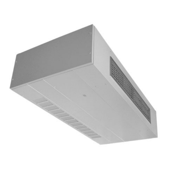
Daikin Classroom Ceiling Unit Ventilators
Ceiling Models AHF, AHB, AHV, and AHR
Digital Ready, MicroTech
Field Control by Others
This manual is to be used as a guide. Each installation is unique, so only general topics are covered.
("J" Vintage)
®
Before beginning installation, please read this publication in its entirety.
Develop a thorough understanding before starting the installation procedure.
The order in which topics are covered may not be those required for the actual installation.
Ventilation rate
certified and tested
per Air Conditioning,
Heating and
Refrigeration Institute
(AHRI) Standard 840.
IMPORTANT!
IM 830-6
Group: Unit Ventilator
Document PN: 910247357
Date: October 2018
Advertisement
Table of Contents

Related Manuals for Daikin IM 830-6


Summary of Contents for Daikin IM 830-6
- Page 1 Installation and Maintenance Manual IM 830-6 Group: Unit Ventilator Document PN: 910247357 Date: October 2018 Daikin Classroom Ceiling Unit Ventilators Ceiling Models AHF, AHB, AHV, and AHR Digital Ready, MicroTech (“J” Vintage) ® Field Control by Others Ventilation rate certified and tested...
-
Page 2: Table Of Contents
Complete Check, Test and Start Procedure ....66 Unit Ventilator Installation ..........18 Installer/Owner’s Responsibility ........66 Tools Required ..............18 Lifting The Unit Into Position ...........19 Anchoring The Ceiling Unit Ventilator ......20 Making Piping Connections ..........21 Coil Connection Locations ..........23 IM 830-6 www.DaikinApplied.com... -
Page 3: Nomenclature
Front Discharge Duct Collar- 36" Length Unit Front Disch. Double Deflection Grille- 36" Length Discharge 16-17 Down Disch. Double Deflection Grille- 40" Length Front Discharge Duct Collar- 40" Length Unit Front Disch. Double Deflection Grille- 40" Length www.DaikinApplied.com IM 830-6... - Page 4 RA Bottom Grille & OA Rear Duct Collar RA Rear Duct Grille & OA Top Duct Collar RA Rear Duct Grille & OA Rear Duct Collar Power Connection Box With Switch Color Off White SKU Type Standard Delivery Product Style 1st Style Change IM 830-6 www.DaikinApplied.com...
-
Page 5: Safety Information
Storage – If equipment is stored for any length of time before servicing. Failure to disconnect power before servicing can cause severe personal injury or death. installation, it should remain in its shipping packaging in a clean, dry, climate controlled area. www.DaikinApplied.com IM 830-6... -
Page 6: Pre-Installation Considerations
If unit is damaged, file a claim with the carrier. Notify the local Daikin Unit Ventilator representative immediately. Properly Identify Unit Ventilator(s) To be sure the correct unit ventilator(s) is/are installed in the... -
Page 7: Ventimatic ™ Shutter Assembly
Shutter Assembly ™ Figure 6: VentiMatic Shutter Assembly VentiMatic Shutter Outside In many installations, a Daikin VentiMatic Shutter Assembly is specified. See Figure 6. This one-way shutter is a continuously variable, gravity actuated, room exhaust vent that operates in direct response to positive static pressure. It opposes any airflow into the room and allows a slight positive pressure. -
Page 8: 40" Deep Unit (750 To 2000 Cfm)
This must be done for each location individually and in maintenance. combination with each other to ensure they are compatible with the 4. All dimensions approximated. specific installation. IM 830-6 www.DaikinApplied.com... -
Page 9: Intake Air Arrangements
Perforated Insulation Vertical Outdoor Air 2. Duct collars shipped loose for field installation not by Daikin. Intake Cover Plate 3. It is important also to verify there is sufficient clearance to open and remove the bottom access panels and end panels for routine maintenance. -
Page 10: Vertical Outdoor Air (Top) Intake Duct Collar Installation
#8 sheet metal screws. #8 x 1-1/4" screws locate within slots on the bottom duct collar angle. Holes provided. Number of screws vary by unit size. Attach angles to unit at holes nearest to the edge. IM 830-6 www.DaikinApplied.com... -
Page 11: Horizontal Room Air (Lower) Intake Duct Collar Installation
Attach angles to unit at as template and drill .125" dia. holes. Attach duct used, duct collar angles holes nearest to the edge. collar angle with provided #8 sheet metal screws. overlap as shown. www.DaikinApplied.com IM 830-6... -
Page 12: Duct System Considerations
Ductwork Sized Based On Airflow Figure 22: Intake/Return Air Duct Work Unit Ventilator Return 5 Feet Same Size As Unit Ductwork Supported Independent Of Unit Return Flexible Boot Acoustically Lined (First 5 Feet from Unit) Two 90-DegreeTurns IM 830-6 www.DaikinApplied.com... - Page 13 Figure 24: Outdoor Air Arrangement With Prevailing Winds Rear Outdoor Air Duct Unit Ventilator Outdoor - prevailing winds Bottom Return Air Top Outdoor Air Duct Unit Ventilator YES! Building Exterior Bottom Return Air www.DaikinApplied.com IM 830-6...
-
Page 14: Installing Louvers
Figure 27: Rear of Horizontal Blade Louver with Bird screens and CAUTION Flange. Locate Drain Lip at bottom of vertical louver to allow proper drainage. For horizontal louvers, the louver blades should face down for proper drainage. Bird screen should always be on side toward unit. IM 830-6 www.DaikinApplied.com... -
Page 15: Typical Installation Methods
See Figure 29. The flashing moisture from getting under the flashing and into the room. should terminate flush with the exterior of the building. Place a bead of caulk under the flashing to prevent moisture from www.DaikinApplied.com IM 830-6... -
Page 16: Installing The Ventimatic Shutter Assembly
A weather-tight seal Materials keeps unwanted air and moisture from entering the occupied Vertical or Horizontal Blade Wall Intake Louver space. See Figure 25 through Figure 35, and Table 2 (Horizontal Blade Shown) various louver details. IM 830-6 www.DaikinApplied.com... - Page 17 3. Optional steel interior wall grille should be used to conceal the interior wall opening whenever the Ventimatic shutter is not located behind shelf cabinets or DraftStop enclosure. Hardware to mount the interior wall grille is not included. www.DaikinApplied.com IM 830-6...
-
Page 18: Unit Ventilator Installation
Use 72" length forklift tines, short tines will damage the unit bottom. Install this product in accordance with good engineering practices and workmanship, following these general instructions, plus the job-specific Daikin submittal drawings provided for specific dimensions, unit arrangements, controls and electrical details, pipe stub-up locations, etc. provided for specific dimensions, unit arrangements, controls and electrical details, pipe stub-up locations, etc. -
Page 19: Lifting The Unit Into Position
5-Row Coil 1.03 (3.90) 1.34 (5.07) 1.64 (6.21) 1.95 (7.38) 1.95 (7.38) Approximate weights based on Face and Bypass Damper Controlled Unit with 4- row cooling coil, high capacity hot water coil and MicroTech II controls. ® www.DaikinApplied.com IM 830-6... -
Page 20: Anchoring The Ceiling Unit Ventilator
Use an 8 foot level to ensure front to back and side to side are level. Twisting can result in unit vibration due to out of alignment of rotating components (fans, fan shaft, and motor). This can also cause premature motor failure. IM 830-6 www.DaikinApplied.com... -
Page 21: Making Piping Connections
When Brazing, to Prevent Overheating The Piping Connection Locations" on page 23 through page 27). Components (Avoid Valve Damage and Erratic Operation) CAUTION Improper water piping to coils can result in improper unit operation and coil freeze-ups. www.DaikinApplied.com IM 830-6... - Page 22 Figure 47: Condensate Drain Viewed from Bottom of Unit with Hinged Access Door Open Suggested Condensate Trapping Daikin cooling unit ventilators are designed for condensate removal into a condensate disposal system. Do not connect the unit drain connection so that condensate exits to the outside and/or is exposed to freezing temperatures.
-
Page 23: Coil Connection Locations
Z = None 66 = 2-row Hot Water Coil 67 = 3-row Hot Water Coil 68 = Low Capacity Steam Coil 69 = High Capacity Steam Coil 12 = Low Electric Heat Coil 13 = High Electric Heat Coil www.DaikinApplied.com IM 830-6... - Page 24 Stream AHV. facilitate piping. (Must be opposite end when using Daikin controls.) V, S, W, Y, 5, 6, 7, 8 5. Cooling condensate connection is same end as cooling coil con- nections, but is field reversible.
- Page 25 69 = High Capacity Steam Coil V or 5 = 2-row CW Coil 12 = Low Electric Heat Coil S or 6 = 3-row CW Coil 00 = None W or 7 = 4-row CW Coil G or 9 = Direct Expansion Coil www.DaikinApplied.com IM 830-6...
- Page 26 W or 7 = 4 Row CW Coil 68 = Low Capacity Steam Coil G or 9 = Direct Expansion Coil 69 = High Capacity Steam Coil 12 = Low Electric Heat Coil 13 = High Electric Heat Coil IM 830-6 www.DaikinApplied.com...
- Page 27 69 = High Capacity Steam Coil 12 = Low Electric Heat Coil 13 = High Electric Heat Coil Note: Direct Expansion (DX) coils have female sweat connections. Interconnecting tubing is by others. Table 9 for correct tubing size. www.DaikinApplied.com IM 830-6...
-
Page 28: Typical Valve Packages
Face & Bypass End of Cycle Valves 2-Way End of Cylce Valve The optional factory-supplied Daikin Control Valve(s) for water applications can be either 2-way or 3-way type, and is / are shipped separate from the unit ventilator itself to help avoid... - Page 29 300 psi (2100 kPa) 13 & 15 psi Close-Off Pressure 13 psi (90 kPa) (90 & 103 kPa) 32°F to 200°F 32°F to 200°F Temperature (0°C to 93°C) (0°C to 93°C) Connection 3/4" (19mm) " (24mm) FNPT www.DaikinApplied.com IM 830-6...
- Page 30 Pressure Drop Across the Valve 2-Way CCV Connection Size 1 PSI 2 PSI 3 PSI 4 PSI 5 PSI 6 PSI 7 PSI 8 PSI 9 PSI 10 PSI Maximum Part No. Rating B209 B210 B211 1/2" B212 B213 B214 IM 830-6 www.DaikinApplied.com...
- Page 31 3 PSI 4 PSI 5 PSI 10 PSI 15 PSI Maximum Size Rating B215HT073 0.73 10.99 13.71 16.11 18.33 28.03 36.74 B215HT186 1.86 22.34 34.93 41.06 46.70 71.42 93.60 1/2" B215HT455 4.55 54.65 85.44 100.43 114.24 174.72 228.97 www.DaikinApplied.com IM 830-6...
- Page 32 Table 24: 2-Way Modulating Steam Valve 3/4" - Pressure Drop Pressure Drop Across the Valve 2-Way CCV Part Connection 2 PSI 3 PSI 4 PSI 5 PSI 10 PSI 15 PSI Maximum Size Rating B220HT731 7.31 3/4 inch 110.02 137.27 161.36 183.54 280.70 367.86 IM 830-6 www.DaikinApplied.com...
- Page 33 Pressure Drop Across the Valve 3-Way CCV Part Connection 1 PSI 2 PSI 3 PSI 4 PSI 5 PSI 6 PSI 7 PSI 8 PSI 9 PSI 10 PSI Maximum Size Rating B309(B) B310(B) B311(B) 1/2" B312(B) B313(B) B318(B) www.DaikinApplied.com IM 830-6...
-
Page 34: Steam Modulating Valve Selection
WHT (Input 2 to 10 VDC) location. The valve should have a pressure drop greater than that of the coil. Locating Rib Note: The actuator spring returns the valve to the open position when the actuator is de-energized (off). IM 830-6 www.DaikinApplied.com... -
Page 35: Typical Piping Arrangements
Return to provide the installing contractor with maximum flexibility in (Bypass) Balancing Valve making the field piping connections. Refer to Daikin factory instruction sheet shipped with the unit for port orientation 3-way Supply EOC Valve and a piping schematic. - Page 36 Notes: clearance to remove the actuator form the valve body. Provide 1. All piping, fittings and unions by others (not Daikin) except as noted. unions for removal of unit coil and/or control valve as a future 2. Supply and return coil connection and stub-up unions by others service consideration.
- Page 37 Table 31: Descriptions for Figure 66 end to facilitate piping. When using Daikin MicroTech controls, 1&2 Shutoff valves (Provided by Others) they must be opposite end. The modulating valve accessory Supply-coil connection and stub-up union must be field installed on the unit for which it was selected.
- Page 38 Units Only) Shutoff Valve Table 33: Descriptions for Figure 70 Supply Three-way modulating control valve (Daikin) Coil (Auto) air vent (Daikin) Note: Actuator to be configured for A port to be normally open. Coil drain (Daikin) Shutoff valves (Provided by Others)
- Page 39 Cooling – Modulating Valve Piping Table 34: Descriptions for Figure 72 Two-way modulating control valve (Daikin) 2-Way Modulating, Normally Closed, Chilled Coil (Auto) air vent (Daikin) Coil drain (Daikin) Water – Typical Shutoff valves (Provided by Others) The 2-way Modulating chilled water valve is furnished normally Balancing shutoff valve(s) (by Others) closed to the coil.
- Page 40 Condensate Piping Figure 74: TXV Valve Piping Detail (Right Hand Shown) Daikin cooling unit ventilators are designed for condensate STOP! Before Brazing removal into a condensate disposal system. Do not connect the unit drain connection so that condensate exits to the outside and/or is exposed to freezing temperatures.
-
Page 41: Split Systems Guidelines
TXV refrigerant flow at lower ambient) • For lower ambient conditions install variable speed condenser fan head pressure control to maintain head pressures between 180psig and 280psig (for proper TXV refrigerant flow at lower ambient). www.DaikinApplied.com IM 830-6... - Page 42 To controls by others, to energize To controls by others, to TDR = Time Delay Relay Factory Wired condensing unit normally open contact energize condensing unit TB = Terminal Block Field Wired (By Others) normally open contact. IM 830-6 www.DaikinApplied.com...
- Page 43 9-11 11-13 9-11 13-15 10-12 15-17 8-10 12-14 18-20 10-12 15-17 21-23 13-15 19-21 24-26 15-17 21-23 26-28 NOTICE Typical conditions - 95°F ambient, 75 psig suction, 285 psig head pressure, 6 - 7° superheat, 15°F subcooling www.DaikinApplied.com IM 830-6...
-
Page 44: Making Control Connections
3. Meets NOTICE the requirements of ANSI/ASHRAE 135-2008 Not all external signal options can be used simultaneously and may standard for BACnet systems not be available on all software models Figure 80: MicroTech Sensor and Component Locations IM 830-6 www.DaikinApplied.com... - Page 45 Available in 2-way or 3-way configurations. Spring return actuators are required for all hot water and steam heating valves. All heating valves are Normally Open (NO) and all cooling valves Normally Closed (NC). (See piping/valve section) www.DaikinApplied.com IM 830-6...
- Page 46 External wiring options - see IM for the different configured options, wiring to be minimum 18 gauge, 90°C. EC motors are factory programmed for specified air flow. Contact Daikin Applied for replacement. Cap extra wire. Switch wire 42A to red wire for 208V operation.
- Page 47 MicroTech Wiring Diagram – Typical Figure 83: Typical MicroTech Wiring Diagram – 208V / 60Hz / 3Ph Note: Figure 84 on page 48 for typical MicroTech service and disconnect wiring and wiring schematic legend. www.DaikinApplied.com IM 830-6...
- Page 48 Figure 84: Typical MicroTech Wiring Diagram – Service and Disconnect – 208V / 60Hz / 3Ph Legend - Symbols Accessory or field mounted component Ground Wire nut / splice Overlap point - common potential wires L1/1.20 Wire link (wire link ID / page # . line #) IM 830-6 www.DaikinApplied.com...
-
Page 49: Microtech Unit Electrical Connections
(B), and (C) show location for Face & Bypass control units. (B) is for 208, 230 and 265 volt horizontal (AH) units. (C) shows location for 460 volt horizontal (AH) units. www.DaikinApplied.com IM 830-6... - Page 50 For sensor terminal wiring details see the installation manual specific Gauge 14 AWG 16 AWG 18 AWG 20 AWG to the sensor being used. Length 800 ft. (244 m) 500 ft. (152 m) 310 ft. (94 m) 200 ft. (61 m) IM 830-6 www.DaikinApplied.com...
- Page 51 Pull the wire through the wall and out of the junction box, and sensor failure. To prevent these conditions, Daikin leaving about six inches free. recommends sealing the conduit leading to the junction Pull the wire through the hole in the base plate.
- Page 52 Daikin Applied recommends using shielded 22AWG for all connections and a separate twisted pair for the power wire All wiring must comply with the National Electric Code (NEC) connections.
-
Page 53: Digital Ready™ - Face & Bypass Control Components Model Ahf
Wired to the Terminal Strips: evaporator coil temperatures. Direct Expansion (DX) units only. Interface with the fan motor start/stop relay (R4): in electric connection box. Figure 91: Component Locations (Horizontal Ceiling Unit Shown) Left End View Bottom View Right End View www.DaikinApplied.com IM 830-6... -
Page 54: Digital Ready™ Wiring Diagram
Output signal of 2 to 10 VDC for position feedback. 8. Cord furnished on right hand connections. 7. Motors are factory programmed for specified air flow. Contact Daikin Applied for replacement. CAUTION Refer to unit wiring diagram located behind the bottom access panel at the right end, for actual wiring. -
Page 55: Digital Ready - Unit Mounted
Face & Bypass 50/60 HZ 35 in.-lb. (independent of Damper Actuator Holding: 1 Watt (class 2 power source) CW = CW with a decrease in signal. load) 24 VDC ±10% CCW = CCW with a decrease in signal. www.DaikinApplied.com IM 830-6... -
Page 56: Digital Ready Unit Electrical Connections
Provide power supply to right end compartment to match by Others unit nameplate. CAUTION Use copper conductors only. Use of aluminum conductors may result in equipment failure and overheating hazards. All wiring in right hand compartment must be class 1 Figure 95: Terminal Strip IM 830-6 www.DaikinApplied.com... -
Page 57: Controls By Others Components
Cuts out below 38°F ± 2°F and automatically resets above 45°F ± 2°F. Responds when any 15% of the Daikin unit ventilators come with factory installed components capillary length senses these temperatures. and wiring. It facilitates the field hookup of controls by others,... - Page 58 DX cooling as lower airflow may increase the risk of coil freeze-up. Variable airflow control should not be used on units with electric heat. Figure 97: 0-10VDC Variable Fan Speed Control 0-10 VDC Control Signal IM 830-6 www.DaikinApplied.com...
- Page 59 Output signal of 2 to 10 VDC for position feedback. 8. Cord furnished on right hand connections. 9. Motors are factory programmed for 0-2 VDC OFF, with 2 volts at 50% nominal and 10 volts at 100% PWM. www.DaikinApplied.com IM 830-6...
-
Page 60: Typical Controls By Others Wiring Diagram - Units With Ec Motor Variable Airflow
Typical operation is to wire from the TB-DX to a normally open relay with the relay closing on control call for cooling. For additional information, contact Daikin Applied Applications. 8. Motors are factory programmed for specified air flow. Contact Daikin Applied for replacement. -
Page 61: Typical Controls By Others Wiring Diagram - 3-Speed Ec Motor
Typical operation is to wire from the TB-DE to a normally open relay with the relay closing on control call for cooling. 8. Motors are factory programmed for specified air flow. Contact Daikin Applied for replacement. CAUTION Refer to unit wiring diagram located behind the bottom access panel at the right end, for actual wiring. -
Page 62: Controls By Others - Electrical Connections
(B), and (C) show location for Face & Bypass control units. (B) is for 208, 230 and 265 volt horizontal (AH) units. (C) shows location for 460 volt horizontal (AH) units. IM 830-6 www.DaikinApplied.com... - Page 63 Typical operation is to wire from the TB-DE to a normally open relay, with the relay closing on control call for cooling. For additonal information, contact Daikin Applied applications. 10. Motors are factory programmed for specified air flow. Contact Daikin Applied for replacement.
- Page 64 Max Fuse Size or Circuit Breaker Electric Heating Amps 14.5 19.3 24.1 14.5 28.9 14.5 28.9 460-60-3 Unit Minimum Circuit Ampacity 10.6 19.6 13.6 25.7 16.6 31.7 19.6 37.7 21.1 39.1 Max Fuse Size or Circuit Breaker Note: Electric heat disconnect provided. IM 830-6 www.DaikinApplied.com...
-
Page 65: Unit Ventilator(S) Start-Up
/ or unusual noises. All panels should be in place and properly fastened. Check for air leaks and condensation. Filter Access and Removal With Daikin’s single-filter design, filter change out takes only minutes. Remove Battery ShippingTab CAUTION... -
Page 66: Install Unit Ventilator End Panels
(Figure 109) monthly or more if conditions indicate. Filters are included in all units. Daikin single-use filters are standard on all but Figure 109: Install End Panels (1" End Panel Shown) electric heat units, which come with permanent wire mesh filters. - Page 67 IM 830-6...
- Page 68 Daikin Applied Training and Development Now that you have made an investment in modern, efficient Daikin equipment, its care should be a high priority. For training information on all Daikin HVAC products, please visit us at www.DaikinApplied.com and click on Training, or call 540-248-9646 and ask for the Training Department.
Need help?
Do you have a question about the IM 830-6 and is the answer not in the manual?
Questions and answers