
Related Manuals for Dynisco UPR800-0-0-3


Summary of Contents for Dynisco UPR800-0-0-3
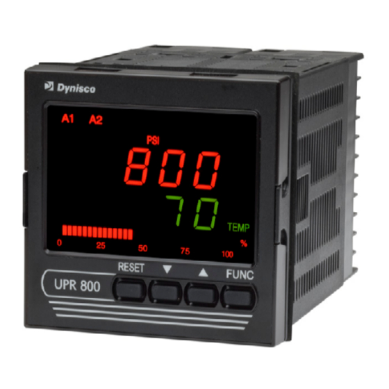
- Page 1 DYNISCO UPR800 Series Instruction Manual UPR800 Series Process Indicator 1/4 DIN Panel Display of Pressure and Temperature P/N: 974144 REV: 04/10 ECO #: 36299 Page | 1...
-
Page 2: Table Of Contents
DYNISCO UPR800 Series Instruction Manual Table Of Contents QUICK START INSTRUCTION ........................5 Mounting ..............................5 Wiring ..............................6 Scaling ..............................6 Calibration and Operation ........................6 1.0 INTRODUCTION ..........................7 2.0 SPECIFICATIONS ..........................8 2.1 Mechanical Specifications ........................ 8 2.2 Main Power Supply &... - Page 3 DYNISCO UPR800 Series Instruction Manual 8.4.3 Setting the Thermocouple Type and Units: ................. 37 8.4.4 Setting the Secondary Input Failsafe Mode ................. 37 8.5 Setting the Alarms: ......................... 38 8.5.1 Setting Channel Alarm to Monitor (Alarm Input Channel Link): ............ 38 8.5.2 Setting Alarm Type: ........................
- Page 4 DYNISCO UPR800 Series Instruction Manual Page | 4...
-
Page 5: Quick Start Instruction
DYNISCO UPR800 Series Instruction Manual QUICK START INSTRUCTION Mounting • Prepare panel cutout to dimensions shown below. • If more instruments are mounted in the same panel near together, maintain the distances between one instrument to another like as in the figure. -
Page 6: Wiring
DYNISCO UPR800 Series Instruction Manual Wiring • Connect the wires from transducer cable as shown in the terminal diagram, turn the screws with a torque between 1.0 and 1.2 Nm. • Connect an appropriate length of thermocouple extension wire (Type J) to the connector. -
Page 7: Introduction
DYNISCO UPR800 Series Instruction Manual 1.0 INTRODUCTION The UPR800 Pressure/Process Indicator is a microprocessor-based instrument, with the capability of monitoring one or two process variables simultaneously. The primary input is user configurable to be 350K Strain Gage, high-level voltage or high level current. If the second input option is chosen, it is configurable by the user as any of four thermocouples, PT-100 RTD, high-level voltage or high level current. -
Page 8: Specifications
DYNISCO UPR800 Series Instruction Manual 2.0 SPECIFICATIONS 2.1 Mechanical Specifications Case: Polycarbonate Black color Self-extinguishing degree VO according to UL 94 Front Panel: Designed and verified for IP65 and NEMA 4X for indoor location Installation: Panel mounting Rear Terminal Block: 43 screw terminals with rear safety cover 2.2 Main Power Supply &... -
Page 9: Display Specifications
DYNISCO UPR800 Series Instruction Manual • Electrostatic discharge (according to EN 61000-4-2): contact discharge = 4kV; air discharge = 8kV • Radio-frequency electrical magnetic (according to EN 61000-4-3): EM field (amplit. mod.) = 10 V/m (80 MHz to 1 GHz);... -
Page 10: Primary Input
DYNISCO UPR800 Series Instruction Manual Indicators (Beacons): Red LED’s annunciations: • A1: Lit when alarm 1 is in alarm state • A2: Lit when alarm 2 is in alarm state • A3: Lit when alarm 3 is in alarm state •... -
Page 11: Secondary Input (Optional)
DYNISCO UPR800 Series Instruction Manual Engineering Units: Dedicated beacons within the display window. Calibration mode: Field calibrations (zero and span) are applicable for both strain gage and linear input. Moreover it is possible to delete the field calibration done by the end user and to restore original factory calibration values. - Page 12 DYNISCO UPR800 Series Instruction Manual Sensor Type and Range: Thermocouple J -200/+800°C -328/+1472°F Thermocouple K -200/+1200°C -328/+2192°F Thermocouple L -200/+800°C -328/+1472°F Thermocouple N 0/1300°C 32/+2372°F Thermocouple T -200/+400°C -328/+752°F Thermocouple E -200/+600°C -328/+1112°F RTD Pt100 -200/+600°C -328/+1112°F RTD Pt500 -200/+600°C -328/+1112°F...
-
Page 13: Primary & Secondary Analog Inputs Common
DYNISCO UPR800 Series Instruction Manual 2.6 Primary & Secondary Analog Inputs Common Common Mode Rejection Ratio: >120dB @50/60Hz Normal Mode Rejection Ratio: >60dB @ 50/60Hz Strain gage input: From 340 to 5000K, 1-4 mV/V. Excitation 10V +/- 7%. 5 wires connection. -
Page 14: Optional Serial Communication Interface Specification
DYNISCO UPR800 Series Instruction Manual AL1 and AL2 Contacts: 1 SPDT 2A max 0 240Vac resistive load. AL3 Contacts: 1 SPST selectable NO/NC 2A max @ 240Vac resistive load. Contact Protection: Varistor for spike protection. Alarm Type: Each alarm is keyboard programmable for: •... -
Page 15: Second Analog Output Specification
DYNISCO UPR800 Series Instruction Manual Type of Output Function: Keyboard selectable as • Primary input retransmission • Secondary input retransmission Type of Analog Output: Keyboard selectable between: • +0/10Vdc min. load 5 KN, with under/over range capability from -2.5 to 12.5V •... - Page 16 DYNISCO UPR800 Series Instruction Manual AUXILIARY MAIN POWER SUPPLY POWER SUPPLY MAIN MAIN ANALOG INPUT ANALOG Strain gage and Linear OUTPUT DISPLAY KEYBOARD SECONDARY SECONDARY ANALOG INPUT ANALOG Tc, RTD and Linear OUTPUT RESET ALARM 1 Logic Input OUTPUT ALARM 2...
-
Page 17: Unpacking
DYNISCO UPR800 Series Instruction Manual 3.0 UNPACKING Upon receipt, examine package for shipping damage. Notify the carrier immediately in the event of any evidence of damage, and retain shipping materials for their inspection. This package should contain the instrument and two panel mounting brackets. -
Page 18: Dimensional Information
DYNISCO UPR800 Series Instruction Manual 4.0 DIMENSIONAL INFORMATION Dimensions: 3.78” X 3.78” X 6.01” overall (96mm X 96mm X 143.5mm) Cutout: 3.62” X 3.62” (92mm X 92mm) Depth behind panel: 5.04” (128mm) Weight: 1.43 lbs. (650g) Page | 18... -
Page 19: Hardware
DYNISCO UPR800 Series Instruction Manual 5.0 HARDWARE The UPR800 is shipped configured for the following: • Primary Input (Pressure) - Strain Gage • Optional Secondary Input - Thermocouple • Main Output - Voltage • Optional Secondary Output – Voltage • Security lock is OFF Please refer to the drawings in the appropriate sections to determine the configuration for input(s) and output(s) used in your particular application. -
Page 20: Mounting And Wiring
DYNISCO UPR800 Series Instruction Manual 6.0 MOUNTING AND WIRING Please refer to figures for cutout dimensions and clearance requirements. Locate the two mounting brackets packed with the instrument and have them available. 1. Slide the instrument case into the cutout, being sure that it is right-side-up (terminal 1 at the top). - Page 21 24Vac/dc). When the fuse is damaged, it is advisable to verify the power supply circuit. It is necessary to send back the instrument to Dynisco for service. The safety requirements for Permanently Connected Equipment say: • A switch or circuit-breaker shall be included In the building installation;...
-
Page 22: Terminal Assignments
DYNISCO UPR800 Series Instruction Manual 6.1 Terminal Assignments Terminal Function Voltage Current Load type and Rating Assignment - category / class Rating, Rating, Description RTD, T/C + 2 Vdc 0.001 Adc RTD, T/C -, mA/V - Secondary Inputs mA +, RTD compensation 0.020 Adc... -
Page 23: Upr700 To Upr800 Wiring Conversion Table
DYNISCO UPR800 Series Instruction Manual 6.2 UPR700 to UPR800 Wiring Conversion Table UPR800 Terminal UPR700 Terminal Power 100 - 240Vac or 24Vac/dc Line Neutral Earth (Ground) Transducer Dynisco Cable Color Signal (+) Signal (-) Black Excitation (+) White Excitation (-) - Page 24 DYNISCO UPR800 Series Instruction Manual UPR800 Terminal UPR700 Terminal 24 VDC Transmitter Power Supply (optional) 24 Vdc (+) 24 Vdc (-) External Reset Contacts Reset Reset Common Second Analog Input (optional) Thermocouple Input TC (+) TC (-) mA Input lnput (+)
- Page 25 DYNISCO UPR800 Series Instruction Manual Page | 25...
- Page 26 DYNISCO UPR800 Series Instruction Manual Page | 26...
- Page 27 DYNISCO UPR800 Series Instruction Manual Page | 27...
-
Page 28: Start-Up Procedure
DYNISCO UPR800 Series Instruction Manual 7.0 START-UP PROCEDURE In general, the UPR800 Pressure/Process Indicator is a microprocessor-based instrument, with the capability of monitoring one or two process variables simultaneously. The primary input is configured to accept a 350N Strain Gage, but can be changed to accept high level voltage or current. -
Page 29: Keyboard Description
DYNISCO UPR800 Series Instruction Manual The keys on the UPR800 must be pressed and released to move about in the configure screens. Do not press and hold a key unless told to do so; simply press the key and release it to advance to the next screen. The arrow keys may be held down to advance rapidly through the values. - Page 30 DYNISCO UPR800 Series Instruction Manual None is intended to access the other groups of parameters, or pressing FUNC again returns to the normal display mode. Each group has its own family of parameters, loosely grouped around the decreasing need to change the parameters. Each group also has the ability to load its own default parameters and the default values of the lower number groups.
-
Page 31: Configuration
DYNISCO UPR800 Series Instruction Manual 8.0 CONFIGURATION 8.1 Parameters The UPR800 parameters are grouped in five sections guarded by three security levels. The more common parameters are in the first groups, with the higher Group numbers for those parameters an operator would not normally modify. Each group can be reset to its default value by two keystrokes. -
Page 32: Setting The Logic Input Configuration (If Supplied)
DYNISCO UPR800 Series Instruction Manual upper display. Press the key until ON 1 shows in the upper display. Press the FUNC key to load all of the factory parameters for groups 1, 2, 3, 4, and 5. To reset a specific group (and higher numbered groups) to the default factory settings,... -
Page 33: Setting The Display Filter
DYNISCO UPR800 Series Instruction Manual parameter, or press the RESET key to go back to the active display. When set to Auto, Group 4 Parameter LINE.R displays the detected Line Frequency. 8.2.5 Setting the Display Filter Filtering is an electrical method of averaging the displayed values over a period of time to arrive at a more legible display. -
Page 34: Primary Input Setup
8.3 Primary Input Setup 8.3.1 Setting the Primary Input Type for a Strain Gage Transducer If using a Dynisco transducer, the model number of the transducer will designate its own electrical output. For example, in plastic melt applications, the PT462E-5M-6/18 or TPT432A-10M-6/18 have a strain gage (0-3.33 mV/V dc full scale) signal output. -
Page 35: Setting The Primary Input Full-Scale Value
DYNISCO UPR800 Series Instruction Manual middle or end number of 4, 5, or 6. The PT140 has a 4-20mA signal output; the PT150- 7.5M has a 0-5Vdc signal output, while PT276-5M has a 0-10Vdc signal output. NOTE: If using 0-10V transmitter, do not connect RCal leads to terminals 14 & 17. -
Page 36: Setting The Primary Input Decimal Place
DYNISCO UPR800 Series Instruction Manual 8.3.6 Setting the Primary Input Decimal Place To set the decimal place, press the FUNC key until nonE and GROUP show on the display. Press the key until 3 shows in the upper display. Press the... -
Page 37: Setting The Thermocouple Type And Units
DYNISCO UPR800 Series Instruction Manual the lower display changes to SI.LO. Using the keys, enter the zero value for the input. For example if the input from a device is 500-3,000 units, it is 500 units at zero, so enter 500. Press the FUNC key to set the value. -
Page 38: Setting The Alarms
DYNISCO UPR800 Series Instruction Manual display shows the correct mode, either HI or Lo. Press the FUNC key to set the value. Finally, press the RESET key to go back to the active display. 8.5 Setting the Alarms: All Alarms supplied with the Instrument can be linked to either the Primary Input or the Secondary Input (if available), and are capable of being set as High Level Alarms or Low Level Alarms, and may operate in either Failsafe or Direct condition. -
Page 39: Setting The Filtering For Alarm 1
DYNISCO UPR800 Series Instruction Manual The default alarm type for Alarm 1 is high. To check or change this value press the FUNC key until nonE and GROUP show on the display. Press the key until 3 shows in the upper display. Press the FUNC key until A1.TYP shows in the lower display. -
Page 40: Setting The Failsafe Mode For Alarms
DYNISCO UPR800 Series Instruction Manual 8.5.6 Setting the Failsafe Mode for Alarms: The Alarm Failsafe Mode determines how the alarms react in the event of a power failure to the UPR800. In the failsafe mode, the alarms will activate in the event of power loss. -
Page 41: Setting The Main Analog Output Type
DYNISCO UPR800 Series Instruction Manual 8.6.1 Setting the Main Analog Output Type The Main Analog Output Type sets the output to specific voltages or currents. The available outputs are 0-20mA, 4-20mA, 0-10Vdc, -10 to +10Vdc, and 0-5Vdc. To change or view this value, press the FUNC key until nonE and GROUP show on the display. -
Page 42: Setting The Security Codes
DYNISCO UPR800 Series Instruction Manual To change or view the Main Analog Output Filter, press the FUNC key until nonE and GROUP show on the display. Press the key until 2 shows in the upper display. Press FUNC key until the lower display changes to MO.FL. Using the keys, select the amount of filtering desired, from none (OFF) to five seconds. -
Page 43: Setting The Security Codes For Level C
DYNISCO UPR800 Series Instruction Manual changes to CODE.C, and the Upper display shows 1. This means that all levels are locked and cannot be changed. 8.7.3 Setting the Security Codes for Level C If you first set CODE.A and CODE.B, the lower display will read CODE.C. If not, press FUNC key to move to CODE.C. - Page 44 DYNISCO UPR800 Series Instruction Manual 4-20mA Transmitter Wiring Diagram For Primary Input (PT1) For Secondary Input (PT2) - SIG - SIG + SIG + SIG 4-20mA 4-20mA 2 wire 2 wire 24 VDC 24 VDC Transmitter Transmitter SUPPLY SUPPLY 0-20mA Transmitter Wiring Diagram...
- Page 45 DYNISCO UPR800 Series Instruction Manual Configuration Parameters are arranged in Groups 5 through 1 and are in order of frequent use. A general rule of thumb Group 5 parameters are modified once during setup of the indicator and gradually increase in frequency of use to Group 1 which includes Alarm thresholds that may be changed on a regular basis.
- Page 46 SHNT.% will be displayed on the lower display (If previous operation set SHUNT to ON). Using the arrows, the % can be adjusted from 40.0 to 100.0 % of full scale. Dynisco Melt Pressure Transducers utilize 80% Shunt Cal output. Consult the manufacturer’s documentation for recommended Shunt Calibration setting if using the controller with other sensors.
- Page 47 DYNISCO UPR800 Series Instruction Manual 3. Press FUNC to save and move to the next parameter. PI.LSV will be displayed. Using the arrows, set the Primary Input Low scale value to the minimum value, typically zero for Melt Pressure sensors.
-
Page 48: Configure By Remote Pc (Configuration Port Interface Or Cpi)
DYNISCO UPR800 Series Instruction Manual 7. Press FUNC button until Process Variable is displayed or press the RESET button to exit Group 2. The remaining parameters in Group 2 relating to Alarm and Retransmission Filters is outlined in Section 8. - Page 49 DYNISCO UPR800 Series Instruction Manual Instrument CPI adapter 5 pins clip connecter for Wall power RS232 Detail of the 5 pins supply polarized clip PC with USB to configuration RS232 software adapter Page | 49...
-
Page 50: Operation
Be sure that the full scale and low scale values (PI.FSV and PI.LSV) have been set to match the range of the transducer and that the SHUNT function is ON and set to the correct percentage (80% for a typical Dynisco transducer). To calibrate the transducer to the instrument, press the... -
Page 51: Calibration Of Analog Inputs Using A Pressure Calibration Source
DYNISCO UPR800 Series Instruction Manual To calibrate the transducer to the instrument, press the FUNC key until nonE and GROUP show on the display. Press the key until 2 shows in the upper display. Press FUNC key and the lower display changes to ZERO.C. The upper display shows OFF. -
Page 52: Instrument Calibration
DYNISCO UPR800 Series Instruction Manual Press the keys until the upper display changes to CLEAr. Press the FUNC to restore the linear factory calibration of the span value. When the legend DSP.FL appears in the lower display, calibration is complete. Press... - Page 53 DYNISCO UPR800 Series Instruction Manual 6.) If the values CANNOT be made to correspond with the values in the Calibration Parameters Summary Table, the instrument must be sent to Dynisco for repair or re- calibration. See the following Calibration Parameter Summary.
- Page 54 DYNISCO UPR800 Series Instruction Manual CALIBRATION PARAMETERS SUMMARY PARAMETER CIRCUIT INPUT TYPE RANGE VALUE NOTE PL.020 Primary Input Current Zero PH.020 Primary Input Current Full scale 20mA P.020 Primary Input Current Verify PL.05 Primary Input Voltage 0-5V Zero PH.05 Primary Input...
-
Page 55: Rs-485 (Optional)
DYNISCO UPR800 Series Instruction Manual - Firmware revision - Pressure input counts - Zero, for the strain gage input (P.ST.ZE) - Span, for the strain gage input (P.ST.SP) - Pressure (P.STR) - Zero, for the linear inputs (P.LN.ZE) - Span, for the linear inputs (P.LN.SP) - Current (P.020) -
Page 56: Protocol Type
If finished, press RESET to return to the operating screen. Further documentation is available in Dynisco’s publication #974089 Modbus/J-Bus Protocol for Dynisco UPR800/ATC880. Please visit www.dynisco.com or contact Dynisco at 800-221-2201 for an electronic copy of this manual. -
Page 57: Error Codes
Correction: De-power the instrument and wait for 60 seconds. On power-on the situation should clear itself. If it does not correct itself de-power again. If the error still remains, send the instrument to Dynisco for repair (See Section 11.) Wrong zero measure. -
Page 58: Open" Error Code And Troubleshooting
Green wire. The Blue (CAL1) wire connects to terminal 14. If the transducer is wired to DHF or (WRSG) Western Regional Strain Gage standards, contact Dynisco Technical Service at 800-221-2201 10.3 Instrument Maintenance REMOVE POWER FROM THE POWER SUPPLY TERMINALS AND FROM... - Page 59 DYNISCO UPR800 Series Instruction Manual patent-pending design allows the instrument to be removed from the case without having to overcome the friction of all terminals on all boards at one time. Initially the CPU board and alarm board will be released, followed by the I/O and digital communication boards.
-
Page 60: Normative References
DYNISCO UPR800 Series Instruction Manual 11.0 NORMATIVE REFERENCES UL 94: Tests for flammability of plastic materials for parts in devices and appliances. EN 60529: Degrees of protection provided by enclosures (IP Code). Nema 250-1991: Enclosures for electrical equipment (1000 Volts maximum). - Page 61 DYNISCO UPR800 Series Instruction Manual Section 11: Voltage dips, short interruptions and voltage variations immunity test IEC 751:1995: Thermometers - References table DIN 43710-1977: Thermocouples - References table IEC 584-1:1995: Thermocouples - References table Page | 61...
- Page 62 DYNISCO UPR800 Series Instruction Manual 12.0 PARAMETER GROUP MENUS Group I Function As Set AL.MSK Alarms Mask Reset SECUR Security Alarm 1 Threshold Alarm 2 Threshold Alarm 3 Threshold PI.VAL Primary Pressure Input Value SI.VAL Secondary Pressure Input Value DEFLT...
-
Page 63: Group 1 Parameters
DYNISCO UPR800 Series Instruction Manual Group 4 Function As Set SHUNT Shunt Calibration SHNT.% Shunt Value Pl.IFS Primary Input Fail Safe SI.IFS Secondary Input Fail Safe A1.HYS Alarm 1 Hysteresis A1.RES Alarm 1 Reset Mode A1.FSM Alarm 1 Failsafe Mode A2.HYS... - Page 64 DYNISCO UPR800 Series Instruction Manual Use u t keys to input the security code; if the selected code Range: matches the programmed code the parameters of the related security level are unlocked. The unlock operation also unlocks the parameters of the lower numbered groups, while the lock operation locks all the parameters.
-
Page 65: Group 2 Parameters
DYNISCO UPR800 Series Instruction Manual LOADING DEFAULT DATA - Group 1 Available: Only if access to level A is allowed. Upper display: Lower display: DEFLT Use u t keys to switch the upper display from OFF to On 1, the... - Page 66 DYNISCO UPR800 Series Instruction Manual Available: Only if SI.TYP is different from ‘OFF’ and SI.FNC is equal to ‘diff.P’. Upper display: Lower display: SPN.2.C Range: keys to switch the upper display from OFF to On then press FUNC key to start the zero calibration. It is also possible to select the 'CLEAr' value to delete the field calibration and then restore factory calibration.
-
Page 67: Group 3 Parameters
DYNISCO UPR800 Series Instruction Manual Upper display: Time constant of the second analog output filter. Lower display: SO.FL Range: OFF, 0.4, 1, 2, 3, 4, 5 sec. Default value: 0.4 sec. LOADING DEFAULT DATA - Group 2 Available: Only if access to level B is allowed. - Page 68 DYNISCO UPR800 Series Instruction Manual SECONDARY INPUT THERMOCOUPLE TYPE - Group 3 Available: Only if SI.TYP is tc Upper display: Selected thermocouple type of temperature input. Lower display: SI.TC Range: tc J, tc CA, tc L, tc N, tc E, tc T. (thermocouple J, thermocouple K (Cromel lumel), thermocouple L, thermocouple N, thermocouple E, thermocouple T.)
- Page 69 DYNISCO UPR800 Series Instruction Manual Upper display: Secondary input full scale value. Lower display: SI.FSV Range: From 0 to the full scale value (4000, 8000, 20000, 40000, 80000 or 99950, according to the pressure input full scale value). Default value: 10000.
- Page 70 DYNISCO UPR800 Series Instruction Manual Default value: Disabled ALARM 3 TYPE - Group 3 Available: Only if A3.LNK is different than OFF. Upper display: Selection of alarm 3 type. Lower display: A3.TYP Range: HI, LO, InhIb. High, low, low with mask at start-up...
-
Page 71: Group 4 Parameters
DYNISCO UPR800 Series Instruction Manual SECOND ANALOG OUTPUT RANGE HIGH - Group 3 Available: Only if SO.TYP is different than OFF. Upper display: Range high for second analog output. Lower display: SO.HI Range: from 0 to PI.FSV (if SO.LNK = PrI.In) from -1000 to 3000 (if SO.LNK - SEc.In). - Page 72 DYNISCO UPR800 Series Instruction Manual SHUNT CALIBRATION - Group 4 Available: Always Upper display: OFF if shunt calibration is disabled, On if shunt calibration is enabled Lower display: SHUNT Range: OFF, On Default value: SHUNT VALUE - Group 4 Available:...
- Page 73 DYNISCO UPR800 Series Instruction Manual Default value: Failsafe mode ALARM 2 HYSTERESIS - Group 4 Available: Only if A2.LNK is different than OFF Upper display: Alarm 2 hysteresis Lower display: A2.HYS Range: From 0.1 to 10.0% of the selected range Default value: 1.0%...
- Page 74 DYNISCO UPR800 Series Instruction Manual Lower display: LI.TYP Range: OFF, AL, P, AL-P. Disabled, alarm reset, peak reset, alarm and peak reset Default value: Alarm and peak reset LOGIC INPUT STATUS - Group 4 Available: Only if LI.TYP is different than OFF.
-
Page 75: Group 5 Parameters
DYNISCO UPR800 Series Instruction Manual Range: 50, 60, und.60 50, 60: when the device is able to detect correctly 50 or 60 Hz line frequency. und.60: automatic detection of the line frequency doesn’t work (e.g. 24V DC power supply); a 60 Hz rejection is assumed. -
Page 76: Group 6 Parameters
DYNISCO UPR800 Series Instruction Manual Range: 0-20, 4-20, 0-10, -10.10, 0-5. 0-2mA, 4-2 mA, 0-10V, 0-5V. Default value: 0-10V. Note: Proper terminal block wiring required SECOND ANALOG OUTPUT SELECTION - Group 5 Available: Only if second output is fitted Upper display:... - Page 77 DYNISCO UPR800 Series Instruction Manual Use u t keys to input security codes. 0 means no security code Range: (the parameters related to level A, level B and level C are always unlocked)1 means no security code (all parameters related to level C are always locked).
-
Page 78: Warranty And Service
NOTE: Before returning any product for repair, please call the Dynisco Customer Service Department at 800-332-2245 or 508-541-9400 (or E-mail: repair@mc.dynisco.com) for a Return Authorization Number. Questions concerning warranty, repair cost, or delivery should be directed to the Dynisco Service Department as well. For further technical assistance, call 800-221-2201...
Need help?
Do you have a question about the UPR800-0-0-3 and is the answer not in the manual?
Questions and answers