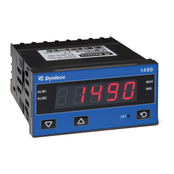
Summary of Contents for Dynisco 1490
- Page 1 From lab to production, providing a window into the process Dynisco 1490 1/8 DIN Indicator Concise Product Manual 59476-9 Operating Manual P/N: n/a Rev: n/a ECO: n/a www.dynisco.com...
-
Page 2: Installation
Replace the instrument by aligning the CPU and PSU boards with their guides in the housing, then slowly push the instrument back into position. NOTE: Option modules are automatically detected at power up. P/N: n/a Rev: n/a ECO: n/a www.dynisco.com... -
Page 3: Panel Mounting
6.0mm (0.25inch) thick. Cut-out sizes are: Cut-Out Dim A = 92mm Cut-Out Dim B = 45mm For n multiple instruments mounted side-by-side, cut-out A is 96n-4mm Tolerance +0.5, -0.0mm P/N: n/a Rev: n/a ECO: n/a www.dynisco.com... - Page 4 The above applies to any and all connection to hazardous mains supply, either direct or indirect (e.g. via a switch or relay). USE COPPER CONDUCTORS (EXCEPT FOR T/C INPUT) Use Screened Cable on Retransmission Option 1 Single Strand wire gauge: Max 1.2mm (18SWG) P/N: n/a Rev: n/a ECO: n/a www.dynisco.com...
- Page 5 1 second then ConF is displayed. You must go into the configuration mode as described in section 3 of this manual. Access to other menus is denied until Configuration Mode is completed. P/N: n/a Rev: n/a ECO: n/a www.dynisco.com...
-
Page 6: Select Mode
, to return to Select mode. Note: Parameters displayed depend on how instrument has been configured. Refer to user guide (available from your supplier) for further details. Parameters marked * are repeated in Setup Mode. P/N: n/a Rev: n/a ECO: n/a www.dynisco.com... - Page 7 From lab to production, providing a window into the process P/N: n/a Rev: n/a ECO: n/a www.dynisco.com...
- Page 8 From lab to production, providing a window into the process P/N: n/a Rev: n/a ECO: n/a www.dynisco.com...
- Page 9 From lab to production, providing a window into the process P/N: n/a Rev: n/a ECO: n/a www.dynisco.com...
-
Page 10: Setup Mode
(while this key is pressed, and for 1 sec after, the parameter legend is shown, then the current value). Press to change the value. To exit from Setup mode, hold down press to return to Select mode. Note: Parameters displayed depends on how instrument has been configured. P/N: n/a Rev: n/a ECO: n/a www.dynisco.com -10-... - Page 11 Press to change the value. To exit from Calibration mode, hold down press to return to Select mode. Note: Calibration mode will only be displayed if input type is set to Str_G P/N: n/a Rev: n/a ECO: n/a www.dynisco.com -11-...
-
Page 12: Special Mode
These messages indicate that the instrument may require attention, or there is a problem with the signal input connection. The message legend is shown for 1 second, followed by its value. Caution: Do not continue with the process until the issue is resolved. P/N: n/a Rev: n/a ECO: n/a www.dynisco.com -12-... -
Page 13: Operator Mode
Note: All Operator Mode parameters in Display strategy 6 are read only (see diSP in configuration mode), they can only be adjusted via Setup mode. P/N: n/a Rev: n/a ECO: n/a www.dynisco.com -13-... - Page 14 From lab to production, providing a window into the process P/N: n/a Rev: n/a ECO: n/a www.dynisco.com -14-...
- Page 15 Max or Min values until they are reset. Once Reset the Max and Min value will follow the displayed value that has gone through the tare process Note: Tare request is aborted if this sequence is not followed exactly. P/N: n/a Rev: n/a ECO: n/a www.dynisco.com -15-...
-
Page 16: Product Information Mode
Hold down and press to return to Select mode. Note: These parameters are all read only. 10. Serial Communications Refer to the full user guide (available from your supplier) for details. P/N: n/a Rev: n/a ECO: n/a www.dynisco.com -16-... -
Page 17: Specifications
If Logic State setting in Config Mode = OPN, Reset or Tare occurs on a Closed to Open transition, or low (<0.8VDC) to high (3 to 5VDC)) transition. Isolation: No isolation from inputs and other outputs. P/N: n/a Rev: n/a ECO: n/a www.dynisco.com -17-... - Page 18 20% to 95% non-condensing. Altitude <2000m Supply Voltage and Power: 100 to 240VAC 10%, 50/60Hz, 9VA (for mains powered versions), or 20 to 48VAC 50/60Hz 9VA or 22 to 65VDC 5W (for low voltage versions). P/N: n/a Rev: n/a ECO: n/a www.dynisco.com -18-...
- Page 19 General information and notices are in this style. FIRMWARE This version of the manual is applicable from firmware version 04 or later. Under the Product Information Mode select I55 to display firmware version. P/N: n/a Rev: n/a ECO: n/a www.dynisco.com -19-...


Need help?
Do you have a question about the 1490 and is the answer not in the manual?
Questions and answers