Table of Contents
Advertisement
Quick Links
OPERATOR'S MANUAL
INCLUDING: OPERATION, INSTALLATION & MAINTENANCE
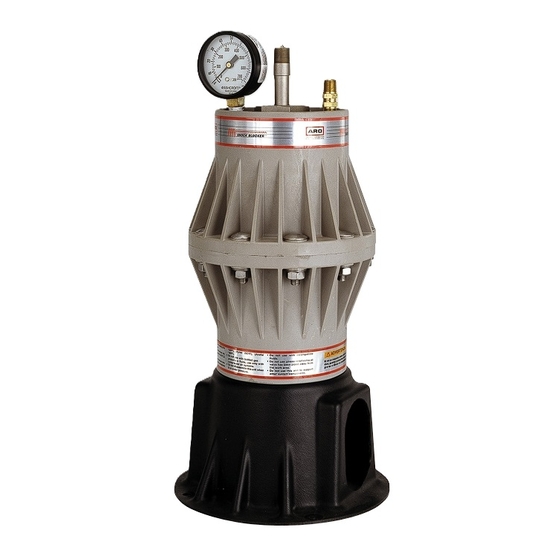
PULSATION DAMPENER WITH ''AIR TAMER" AUTO ADJUSTMENT
It is the responsibility of the employer to place this information in the hands of the operator. Keep for future reference.
SHOCK BLOCKER DATA
Models
. . . . . . .
see ``Model Description Chart" for `` XXX X''.
Pulsation Dampener Type
. . . . . . . . . . .
Material
. . . . . . .
see ``Model Description Chart".
Weight
. .
Glass Filled Polypropylene
Conductive Acetal
Pure Kynar
. . . . . . . . . . . . . .
Maximum Fluid Inlet Pressure
Maximum Air Inlet Pressure
Maximum Fluid Volume
. . . . . . . . . . . . .
Maximum Temperature Limits
Glass Filled Polypropylene
Conductive Acetal
. . . . . . . .
Pure Kynar
. . . . . . . . . . . . .
Air Inlet
. . . . . . . . . . . . . . . . . . . . . . . . .
Material Inlet
. . . . . .
SB10X AXS X
SB10X BXS X
Dimensional Data
. . . . . . . . . . . . . . . . .
Kits Available
66911 1 Air Tamer Automatic Air Pressure Adjustment Kit
66108 Mounting Pedestal
66885 1 Grounding Kit (for use with model SB10D XDS X,
includes 25' 14 gauge wire).
GENERAL DESCRIPTION
The ARO Shock Blocker, pulsation dampener is designed to work with
1:1 ratio pumps having an outlet pressure not exceeding 100 p.s.i. (6.9
bar). The Shock Blocker will effectively reduce material pressure varia
tions, surges and shock to piping and delivery in fluid systems during
pump reversal. It can significantly contribute to pulse reduction in low
pressure spray applications.
Accurate selection of wetted material will assure longest service life
and minimize down time. Several material options are available for the
body and bladder materials. Body materials available include: Polypro
pylene, Conductive Acetal and Pure Kynar. Use Conductive Acetal and
ground cable when pumping flammable materials.
The Shock Blocker uses a single air pressurized, flexible bladder work
ing against the fluid line pressure. Several bladder material options are
available to allow custom matching to the fluid material for best compat
ibility (refer to the model description chart).
The use of an air tamer for a higher level of automatic pressure adjust
ment and accuracy is important. It uses a sensing rod to detect the posi
tion of the bladder and an automatic air valve to adjust the air line
pressure or to exhaust excessive pressure in the bladder chamber as
needed. An air pressure gauge is standard to monitor the air side inter
nal chamber pressure.
Shock Blocker units can also be added in series to provide additional
dampening on the material.
INGERSOLL-RAND COMPANY
P.O. BOX 151
T
&
(419) 636-4242
''SHOCK BLOCKER
READ THIS MANUAL CAREFULLY BEFORE INSTALLING,
OPERATING OR SERVICING THIS EQUIPMENT.
Non Metallic
. . .
8.4 lbs (3.8 kgs)
. . . . . . . . .
8.6 lbs (3.9 kgs)
9.0 lbs (4.1 kgs)
. . . . . . . .
100 p.s.i.g. (6.9 bar)
. . . . . . . . .
100 p.s.i.g. (6.9 bar)
57 in.
(.93 l)
#
. .
35_ to 150_F (2_ to 66_C)
10_ to 180_F ( 12_ to 82_C)
10_ to 200_F ( 12_ to 93_C)
3/8 18 N.P.T.F. 1 (male)
. . .
1 11 1/2 N.P.T. (female)
. . .
1 11 BSP (female)
see page 7.
ONE ARO CENTER
BRYAN, OHIO 43506 0151
D
D
D
FAX (419) 633-1674
R
''
MODEL DESCRIPTION CHART
AIR SECTION MATERIAL
D - Conductive Acetal
K - PVDF (KynarR)
P - Glass Filled Polypropylene
THREAD
A - N.P.T.
B - BSP
FLUID SECTION MATERIAL
D - Conductive Acetal
K - PVDF (Kynar)
P - Glass Filled Polypropylene
HARDWARE MATERIAL
S - Stainless Steel
BLADDER MATERIAL
A - SantopreneR
T - T.F.E.(TeflonR)
U - Polyurethane
Shock BlockerR is a registered trademark of the ARO Corporation.
E
2000 D PRINTED IN U.S.A.
SB10X-X
RELEASED:
3-21-00
REVISED:
(REV. )
SB10 X X X S X
Advertisement
Table of Contents

Related Manuals for Ingersoll-Rand SHOCK BLOCKER


Summary of Contents for Ingersoll-Rand SHOCK BLOCKER
- Page 1 An air pressure gauge is standard to monitor the air side inter nal chamber pressure. Shock Blocker units can also be added in series to provide additional dampening on the material. Shock BlockerR is a registered trademark of the ARO Corporation.
-
Page 2: Operating And Safety Precautions
INSTALLATION INSTRUCTIONS The material flow should be in the direction of the Shock Blocker, for best results, not passing by at right angles (see figure 1, page 3). WARNING HEED WARNINGS AS SHOWN IN ``OPERATING Use the mounting base as provided and additional mounting kit 66108 AND SAFETY PRECAUTIONS'' ABOVE. -
Page 3: Operation
Discontinue use. This would indicate possible fluid incompatibility with the Shock Blocker body material. INSTALLATION MOUNTING CONFIGURATIONS Installation Note: The material flow should flow directly towards the Shock Blocker, not at a right angle to the flow path. SINGLE UNIT MULTIPLE UNIT... - Page 4 (1/4" 20 x 5 1/5") 104 Cylinder Assembly 66886 1 66911-1 AIR TAMER ASSEMBLY NOTE: The Shock Blocker should be supplied with air from the pump's der. air supply. 2. Thread the air tamer into the end cap by hand to insure good en 1.
- Page 5 PARTS LIST / SB10X-X SB10X XXS T . 15 Torque Sequence . Torque Requirements , Lubrication (15) Tighten to 50 60 in. lbs (5.6 6.8 Nm) then Apply Key Lube grease (93706 1). re torque. Do not overtighten fasteners. Apply Loctite 242 to threads. (104) Torque to 25 ft lbs (33.9 Nm).
- Page 6 SHOCK BLOCKER PERFORMANCE 1" PUMP WITHOUT SHOCK BLOCKER 1/2" PUMP % REDUCTION IN PULSATION (From lower chart at right) Flow (G.P.M.) 1" PUMP % REDUCTION IN PULSATION 1" PUMP WITH SHOCK BLOCKER (From lower chart at right) Flow (G.P.M.) Figure 4...
-
Page 7: Dimensional Data
DIMENSIONAL DATA All dimensions are given in inches and (millimeters). 3/8 18 N.P.T.F. 1 Air Inlet 1/4 18 N.P.T. Relief Valve 2 19/32" (65.8 mm) 1 7/32" (31 mm) 10 1/2" (266.7 mm) 13 1/2" (342.8 mm) 5 9/32" (134 mm) Figure 6 7 1/2"... - Page 8 PN 97999 907 PAGE 8 OF 8 SB10X X...
Need help?
Do you have a question about the SHOCK BLOCKER and is the answer not in the manual?
Questions and answers