Table of Contents
Advertisement
Advertisement
Table of Contents

Related Manuals for Bull Outdoor ANGUS 47628


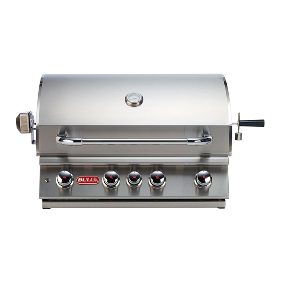
Summary of Contents for Bull Outdoor ANGUS 47628
-
Page 2: Table Of Contents
PAGE# TABLE OF CONTENTS SAFETY INSTRUCTIONS ........, ...., .., ...., ............2 THE LOCATION F0R YOUR GRILL..................................CHECKING FOR GAS LEAKS ..................NATURAL GAS SAFETY ...................., ........... PROPANE GAS SAFETY ............................4 INSTALLATION INSTRUCTIONS ............................ -
Page 5: Safety
Your Propane gas (G31) grillis designed to operate on propane gas elNtY, at a pressure regulated at 11" water column (W.C.)/27.4 mbar/2.74 KPa when equipped with the correct propane orifices on the valves and a propane regulator on the supply line. In the United States, the liquid propane orifice size is 1.18mm. -
Page 9: Installation Instructions
INSTALLATION INSTRUCTIONS (CONT.) OUTDOOR PROPANE GAS BBQ INST ALLA 'FION SPECIF/CATIONS NOTE: - Vents must be provided for combustion air and ventilation on both sides of built-in cabinet. - When choosing a location for your gas grill keep in mind that it should never be located under any overhead combustible construction. - The sides and back of the grill should not be any closer than 21 inches/54 cm/533 mm to combustible construction. - Page 10 INSTALLATION INSTRUCTIONS )CONT.) If using a LP gas tank, thelank must be properly secured within the structure to prevent being knocked over. " ' s . . TANK RETENT --..TANK RETENTION BOLT The tank retention system must be securely fastened to the bottom of the island with the use of bolts, washers and nuts. There must be a minimum clearance of 2 inches/5 cm/50 mm between the floor and the cylinder enclosure.
-
Page 12: Clean
INSPECTING / CLEANING BURNERS AND GAS VALVE ORIF\C S CAUTION -Always turn off the gas supply prior to clearing your grill. BURNER CLEANING 1. Remove burner from the grill insert (See drawing below). Bend a stiff wire (a light-weight coat hanger works well} into a small hook as shown to the right. -
Page 13: Burner Replacement Into Insert
INSPECTING / CLEANING BURNERS AND GAS VALVE ORIFICES (CONT.) _:=-.::::.::1 BURNER REPLACEMENT /Nro /NS�RT- .____:�_:;- _ CAUTION - Always turn off the gas supply prior to clearing your grill. 1. Replace burner back into the grill insert. There i s no need to replace the cotter pin back into the cast peg, it is for shipping purposes only. 2. - Page 14 INSPECTING / CLEANING BURNERS AND GAS V#JLVE ORIFICES {OONl:.) 2. Light any burner by pushing:)ts control knob i n fully and slowly (.3 to 4 seconds) turning it about 1/4 turn to the left (counter-clockwise) until a click is heard. The 3 to 4 secoriclauration should provicle enough gas to lig t tf\e burner. If tiie"6'uiner does not light, immediately return the control knob to "OFF", wait several minutes for the gas to disperse, and repeat the process.
-
Page 15: Cooking Component Installation
COOKING COMPONENT INSTALLATION IMPORT ANT: Before first use: wash flame tamers, cooking grids, and warming rack with warm, soapy wale . Ripse and dry thoroughly. Season metal surfaces with cooRing oil occasionally. (After cooking is completed, turn grill to high setting for NO MORE HAN five minutes to burn off excess grease or food residu CAUTION: DO NOT LEAVE GRILL UNATTENDED WHILE GRILL IS IN USE 1. -
Page 21: Light System
LIGHT SYSTEM CONT.) 4. Using a soft cloth or paper towel, replace new light bulb into the housing (finger prints left on the bulb ay reduce its life). Make sure t7e metal ..prongs on the light bulb slip into the openings in the light housing. 5. - Page 22 Wiring diagram: 1A- Black wire; 18- Red wire; 1C i3lue wire; 1D - Yellow wire PUSH BUTTON SWITCH WIRE HARNESS WIRE HARNESS ------- WIRE HARNESS CONNECTOR LEFT LIGHT HOUSING Detail F CONNECTOR BINDING POST WIRE HARNESS WIRE HARNESS TRANSFORMER PIGTAIL WIRE HARNESS WIRE HARNESS Detail G...
-
Page 23: Cleaning & Maintenance
CLEANING & MAINTENANCE CLEANING COOKING GRIDS After cooking, turn control knobs to "OFF" and let gryll cool befor attempting to clean your cooking grids Before firsf use and periodically it is suggested that you wash the cooking grids in a mild soap and warlJl water solution. You can use a washcloth or a Yegetable brush to clean your cooking grids. -
Page 25: Troubleshooting
TROUBLESHOOTING (CONT.) <al/' YELLOW FLAME Once the entire burne is operating, check the flame color to be sure ii is mostly blue (some yellow color will be prese t because of impurities in the fuel). If the flame is golden or yellow in color the reason could be seasoning salts, oil film, or other foreign matte on bume CORRECTION: Either wash burner with mild detergent, or operate burner at "HIGH"... -
Page 26: Locations Of Serial Number
LOCATIONS OF SERIAL NUMBER Essential information about y o J product is encoded in the seri I number of{our grill. Jhis information will be required for all warranty claims, ordering replacement parts and will 'dentify any variations of yo r unit. It is extremely important that you reGord your serial number and register your grill from the Proof of Purchase. -
Page 27: Parts List
PARTS LIST MODEL #47628 ANGUS 4 BURNER STAINLESS STEEL, ROTISSERIE, BUILT-IN, L.P. (PROPANE) MODEL #47629 ANGUS 4 BURNER STAINLESS STEEL, ROlilSSERIE, BUILT-IN, N.G. (NATURAL GAS) MODEL #47628CE ANGUS 4 BURNER STAINLESS STEEL, ROTISSERIE, BUILT-IN, L.P. (PROPANE) MODEL #47629CE ANGUS 4 BURNER STAINLESS STEEL, ROTISSERIE, BUILT-IN, N.G. (NATURAL GAS) MODEL #47628AGA ANGUS 4 BURNER STAINLESS STEEL, ROTISSERIE, BUILT-IN, L.P. - Page 29 ODED ILLUSTRATIO...
Need help?
Do you have a question about the ANGUS 47628 and is the answer not in the manual?
Questions and answers